
Conduit and a method of cleaning a conduit

a conduit and conduit technology, applied in the field of conduits, can solve the problems of complicated and complicated milking devices, large number of different parts, and use of relatively expensive pressurized air in milking devices, and achieve the effects of simple and efficient cooling of milk, simple and efficient cleaning of conduits, and simple and efficient milking devices

Inactive Publication Date: 2015-04-07
LELY PATENT
View PDF11 Cites 4 Cited by
  • Summary
  • Abstract
  • Description
  • Claims
  • Application Information

AI Technical Summary

Benefits of technology

[0025]It is an object of the present invention to provide a conduit which makes a simpler and more inexpensive milking device possible and, for example, makes simpler and more efficient cleaning of the conduit possible. It is a further object to provide a conduit by means of which simple and efficient cooling of milk during transportation is made possible.

Problems solved by technology

Such a milking device has the drawback that it is relatively complicated and comprises many different parts.
The milking device furthermore uses relatively expensive pressurized air or something similar in order to empty the conduit.

Method used


Image

  • Conduit and a method of cleaning a conduit
  • Conduit and a method of cleaning a conduit
  • Conduit and a method of cleaning a conduit

Examples


Embodiment Construction

[0080]Various embodiments will be discussed in more detail below with reference to the figures. In the figures, the conduits have a substantially round outer periphery. However, an elliptic outer periphery or any other suitable outer periphery is also conceivable and falls within the scope of the invention.

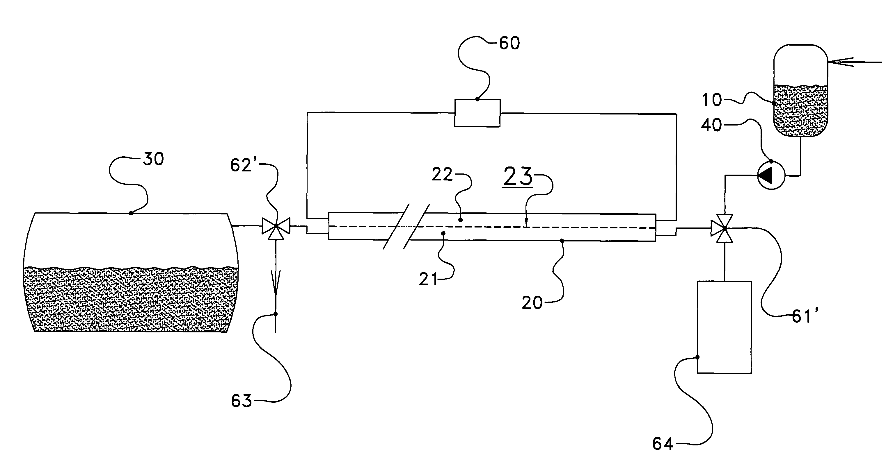
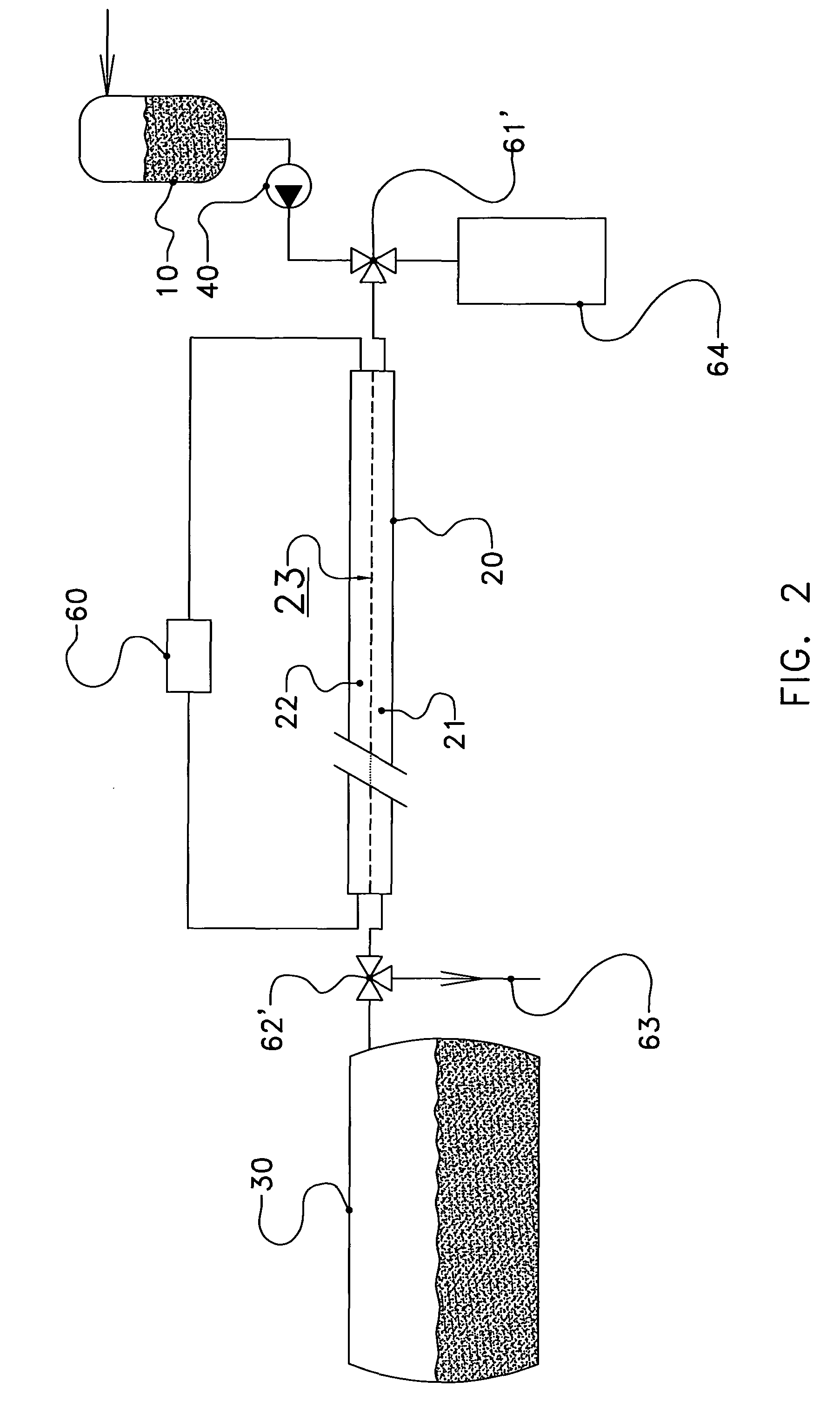
[0081]FIG. 2 diagrammatically shows an embodiment, in which similar elements are denoted by the same reference numerals as in FIG. 1.

[0082]FIG. 2 shows a conduit 20 which is subdivided into a milk duct 21 and a secondary duct 22 by means of a flexible wall 23.

[0083]On an inlet side of the milk duct 21, a first distribution valve 61′ is provided. The first distribution valve 61′ can be moved to a[0084]first position, in which the milk duct 21 is connected to the milking glass 10,[0085]second position, in which the milk duct 21 is connected to the cleaning liquid supply 64.

[0086]On an outlet side of the milk duct 21, a second distribution valve 62′ is provided. The second distributi...


PUM


Abstract

The invention relates to a conduit for transferring milk. The conduit is provided with at least one flexible wall, which divides the conduit into at least one milk duct and at least one secondary duct. The milk duct and the at least one secondary duct extend along a longitudinal axis of the conduit, it being possible for the at least one milk duct to be substantially emptied by pressing through filling the at least one secondary duct.

Description

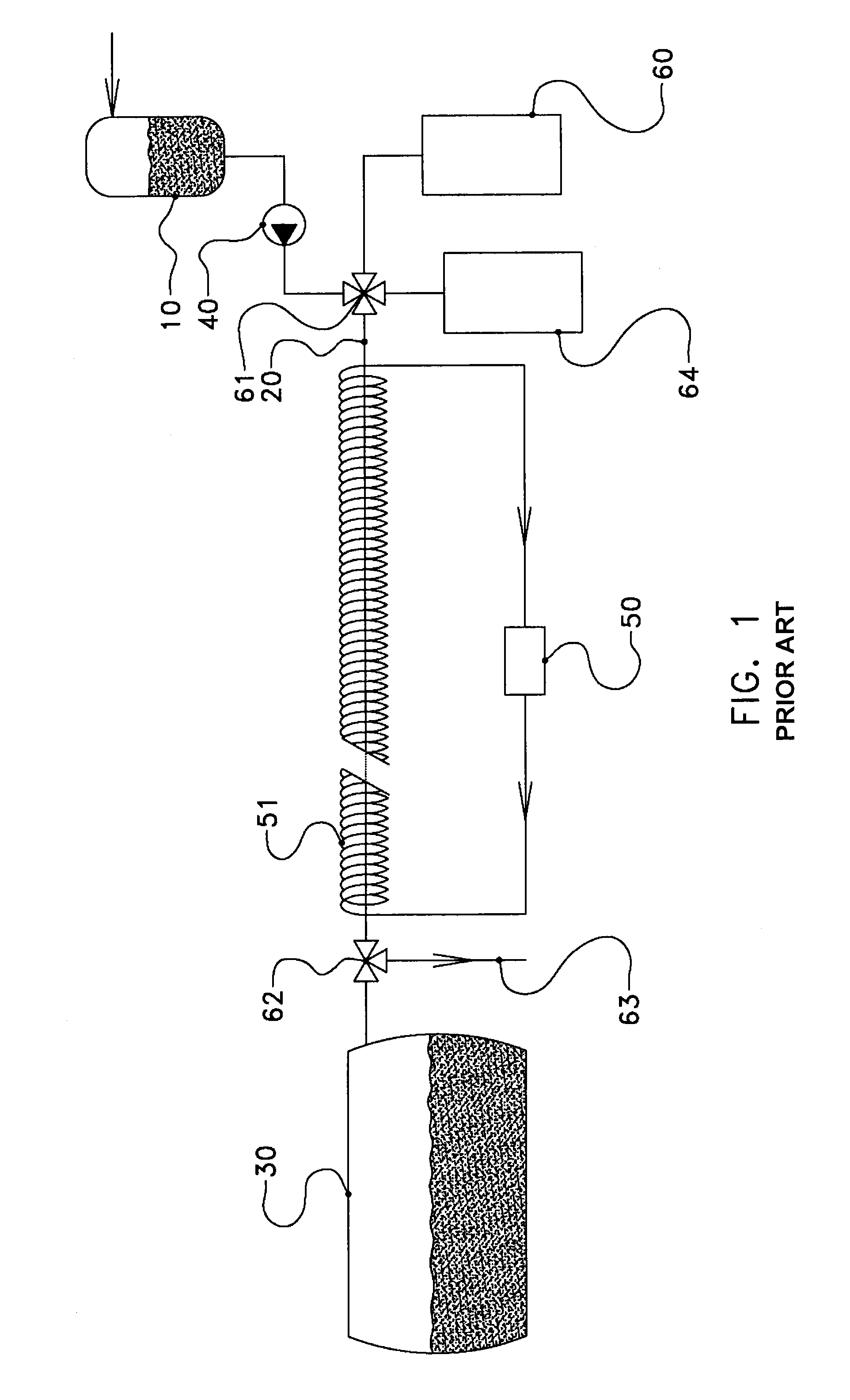
TECHNICAL FIELD[0001]The present invention relates to a conduit for transferring milk. The invention further relates to a milking device comprising such a conduit, a method of cleaning such a conduit and a method for transferring milk through such a conduit.PRIOR ART[0002]Milking devices are used for milking dairy animals.[0003]FIG. 1 diagrammatically shows a part of a milking device 1 according to the prior art. The milking device 1 comprises a milking glass 10 in which the milk obtained from a dairy animal is collected. FIG. 1 does not show the part of the milking device 1 which is configured to suck the milk from the dairy animal and transport the milk obtained to the milking glass 10.[0004]Further, FIG. 1 shows that the milking glass 10 is connected to a further milk container 30, for example a milk tank 30, by means of a conduit 20. The milk tank 30 can be used to collect milk obtained during different milkings from different dairy animals and / or milking glasses and store it. T...

Claims


Application Information

Patent Timeline
Patent Type & Authority Patents(United States)
IPC IPC(8): A01J7/02F16K49/00A01J5/04F16L11/12F16L11/22
CPCA01J7/022A01J5/044F16L11/12F16L11/22Y10T137/4259Y10T137/0318Y10T137/6579Y10T137/6416Y10T137/0419A01J5/00A01J7/00A01J7/02A01J11/00F16L9/18
Inventor MOSTERT, GERARD
Owner LELY PATENT
Learn More