
Plastic spout

a technology of plastic spouts and spouts, which is applied in the field of plastic spouts, can solve the problem that the heat supplied during sealing cannot be dissipated, and achieve the effect of improving the sealing effect and improving the sealing

Inactive Publication Date: 2007-12-06
SHOWA MARUTSUTSU CO LTD
View PDF16 Cites 0 Cited by
  • Summary
  • Abstract
  • Description
  • Claims
  • Application Information

AI Technical Summary

Benefits of technology

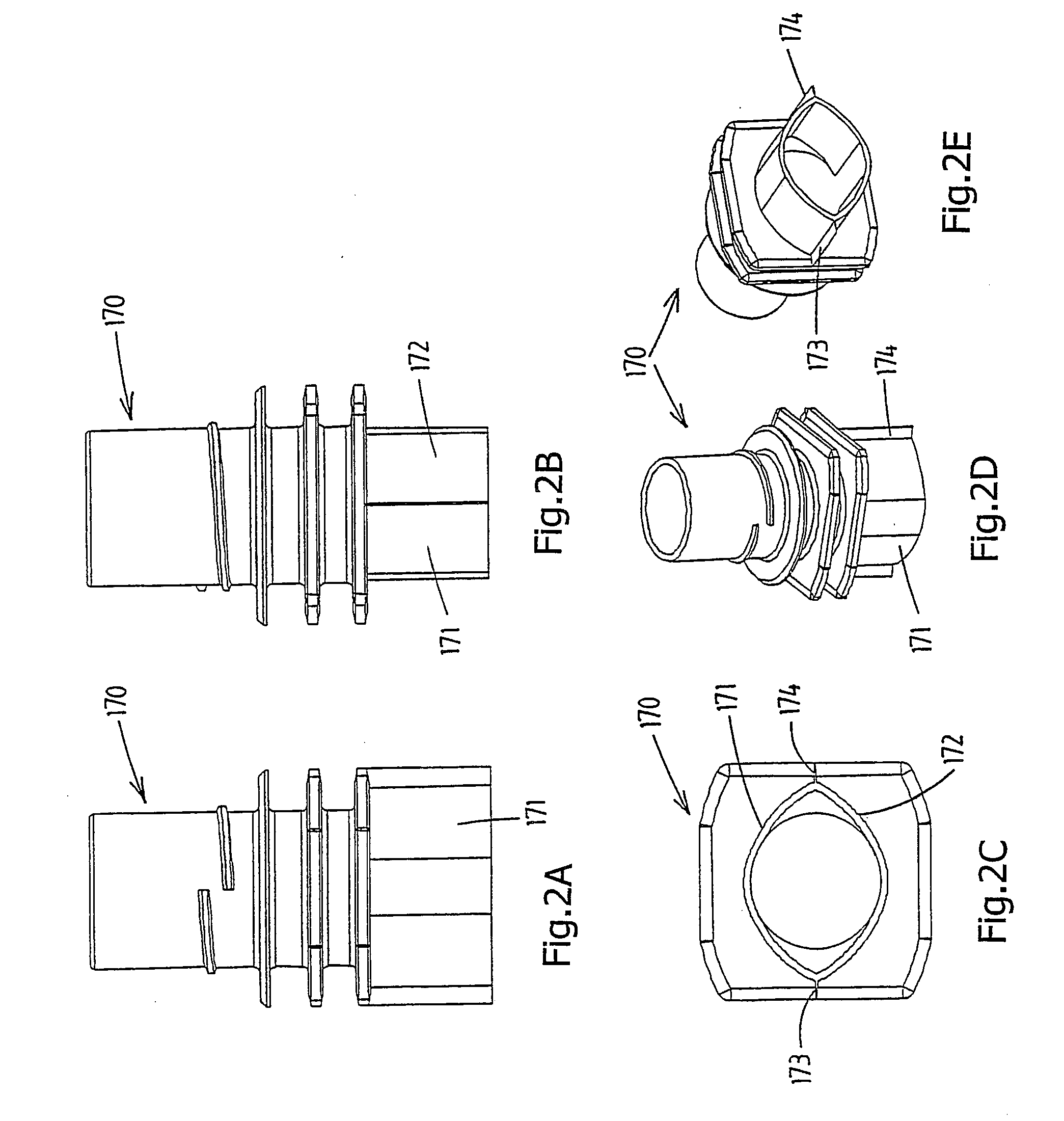
[0013] This design of the sealing walls means that the sealing walls are stable if, during the sealing operation, external pressure is applied to the sealing walls by means of pressure-exerting means, such as heated sealing jaws. Even with a low thickness of the sealing walls (less than 2 millimetres), this stability is such that there is no need to use a support member during the sealing operation, with the result that the support member is preferably omitted.
[0016] Further advantages of the spout with sealing walls according to the first aspect of the invention relate to the production of the spout in a suitable injection mould. This mould can be of relatively simple design, and furthermore the sealing walls require little plastic material. It is also possible for the cooling time for the sealing walls in the mould to be short, which is advantageous with regard to the production rate and cost price. Moreover, on account of the sealing walls, the mould can be provided with simple and efficient cooling means. In particular, the mould part which defines the inner side of the sealing walls and is composed of one or more components can be designed with a relatively large volume of material, so that there is space for efficient cooling means therein.
[0018] It is preferable for the spout to be designed in such a manner that the sealing walls can move flexibly transversely with respect to their plane and on their inner side to be unsupported or supported by one or more flexible supporting parts of the spout body. Then, after the spout has been fitted in the pouch, these sealing walls have a shock-absorbing capacity and can yield elastically with foil walls of the pouch. This reduces the risk of damage to and possible leaks from the pouch at the location of the transition from the foil wall to a sealing wall. Furthermore, the flexibility of the sealing walls is advantageous for the production of the sealed connection, for example because broader dimensional tolerances of the spout body are acceptable without having an adverse effect on correct operation of the sealing device.
[0024] A third aspect of the invention provides a spout which is characterised in that the transverse wall is provided with one or more corrugations transversely with respect to the plane of the transverse wall, which impart flexibility to the transverse wall, in such a manner that the transverse wall allows the flexible movement of the sealing walls. The result of this measure is that the transverse wall does not cancel out the intended flexibility of the sealing walls, so that the shock-absorbing capacity and the sealing properties are positively influenced compared to a transverse wall which is of rigid design.

Problems solved by technology

This is because the heat which is supplied during sealing cannot be dissipated to parts of the spout which lie further away from the surface which is to be melted.

Method used


Image

  • Plastic spout
  • Plastic spout
  • Plastic spout

Examples


Embodiment Construction

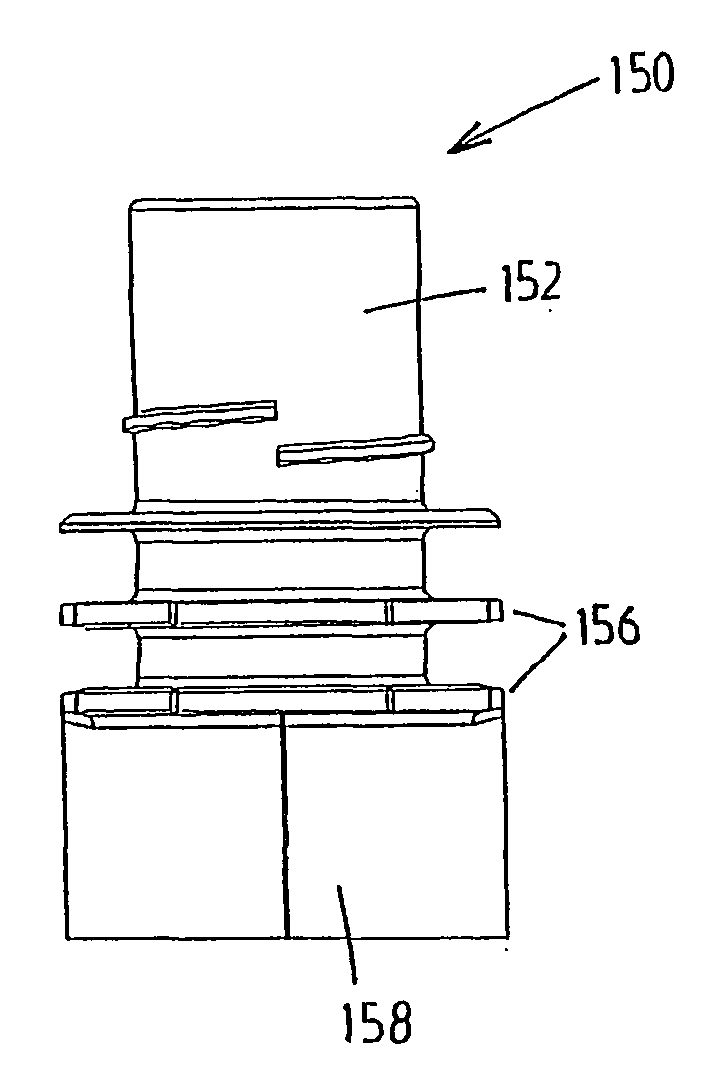
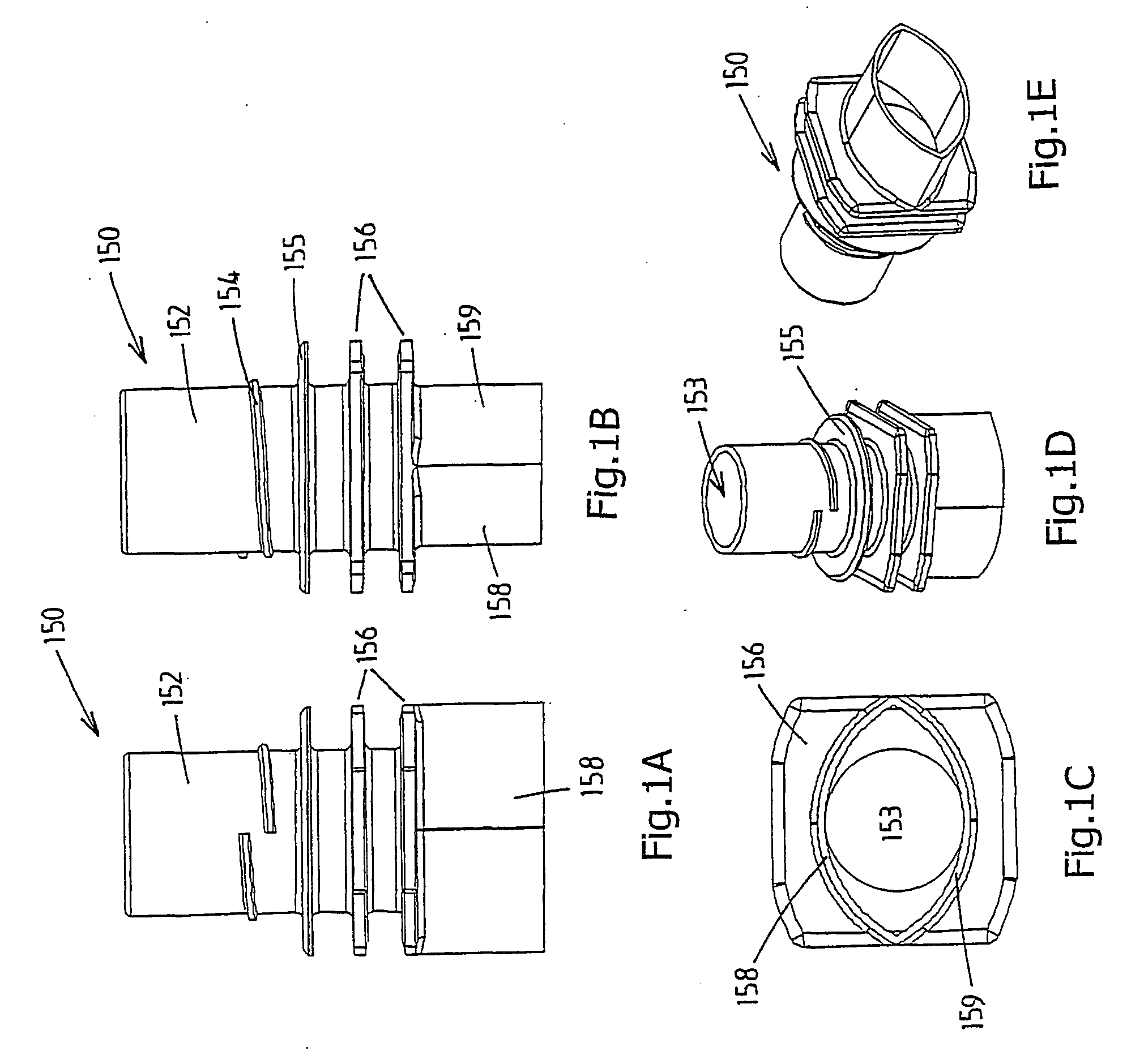
[0047]FIGS. 1a-e show a spout 150 which is produced by injection-moulding from a suitable plastic material and which is intended to be sealed between two foil walls of a pouch.

[0048] The spout 150 has a single-part spout body with, on the top side, an outwardly projecting tubular part 152 which forms a passage 153 for delivering a medium from the pouch and / or feeding a medium to the pouch.

[0049] The tubular part 152 is provided with a screw thread 154 for a screw cap (not shown), which can be used to close off the spout 150.

[0050] The outwardly projecting tubular part 152 is furthermore provided with a locking flange 155 for the screw cap and, beneath this, two circumferential flanges 156 which are used for handling means for the spout 150 and the pouch to engage on after the spout 150 has been sealed in the pouch.

[0051] On the underside, the spout 150 is provided with two sealing walls 158, 159 which project freely downwards, adjoin one another at their diametrically opposite e...


PUM

PropertyMeasurementUnit
thicknessaaaaaaaaaa
thicknessaaaaaaaaaa
flexibleaaaaaaaaaa

Abstract

A plastic spout which is adapted to be sealed between two foil walls of a pouch. The spout has a spout body, which forms a passage for delivering a medium from the pouch and / or feeding a medium to the pouch. In a bottom part thereof, the spout, on opposite sides, forms a sealing zone for a sealed connection to an adjoining foil wall. The sealing zones of the spout body are formed by sealing walls which project downward from the spout body. The sealing walls can preferably move flexibly transversely with respect to their plane and, on their inner side, are unsupported or are supported by one or more flexible supporting parts of the spout body.

Description

CROSS-REFERENCE TO RELATED APPLICATIONS [0001] This application is a divisional application of U.S. patent application Ser. No. 10 / 492,474 filed on Apr. 12, 2004, which is the national stage filing under 35 U.S.C. §371 of PCT / NL02 / 00646, filed Oct. 10, 2002, which claims priority to NL 1019161, filed Oct. 11, 2001, which is incorporated herein by reference.FIELD OF THE INVENTION [0002] The present invention relates to a plastic spout which is intended to be sealed between two foil walls of a pouch, comprising a spout body which forms a passage for delivering a medium from the pouch and / or feeding a medium to the pouch, which spout body, on opposite sides, forms a sealing zone for sealed connection to the adjoining foil wall. [0003] The present invention also relates to a method for sealing a plastic spout between two foil layers of a pouch. BACKGROUND OF THE INVENTION [0004] WO 00 / 66448, in particular FIGS. 9a-d, in the name of the present applicant has disclosed a plastic spout, wh...

Claims


Application Information

Patent Timeline
Patent Type & Authority Applications(United States)
IPC IPC(8): B31B19/84B65D33/38B65D75/58B65D77/30
CPCB65D75/5883B65D25/48Y10S383/906B65D2575/583
Inventor LAST, LAURENS
Owner SHOWA MARUTSUTSU CO LTD
Learn More