Lens module and image apparatus

a technology of lens module and image apparatus, which is applied in the field of optical equipment, can solve the problems of fuzzy images captured during night (in infrared mode), insufficient auto-focusing of video cameras for surveillance, and insufficient zoom magnification of images, etc., and achieves good image-capturing effect, high zoom magnification, and high revolution

Active Publication Date: 2015-04-07
YOUNG OPTICS
View PDF17 Cites 10 Cited by
  • Summary
  • Abstract
  • Description
  • Claims
  • Application Information

AI Technical Summary

Benefits of technology

[0008]Accordingly, the invention is directed to a lens module with high performance of imaging quality.
[0009]The invention is also directed to an image apparatus with good 24-hours confocal image-capturing quality.
[0032]Based on the description above, in the lens module and the image apparatus of the invention, the five lens groups all include at least one positive lens and at least one negative lens, the refractive-powers of the five lens groups are sequentially positive, negative, positive, positive and positive. Moreover, each lens of the third lens group is a spherical lens. In this way, in addition to having high zoom magnification and high revolution, the lens module and the image apparatus of the invention can obtain good image-capturing effect under the different wavelength ranges of the object light-beam.

Problems solved by technology

In the application practice however, the images captured during day normally are clear, while the images captured during night (in infrared mode) are fuzzy.
The different results are caused by a too large difference between visible light and infrared light in wavelength.
In more details, after the visible light and the infrared light pass through a lens module of the video camera, due to the two focal planes of the above-mentioned two lights are apart quite far from each other; in addition, due to the cost consideration, most of the commercial video cameras for surveillance are not equipped with auto-focusing function.

Method used


Image

  • Lens module and image apparatus
  • Lens module and image apparatus
  • Lens module and image apparatus

Examples


first embodiment

The First Embodiment

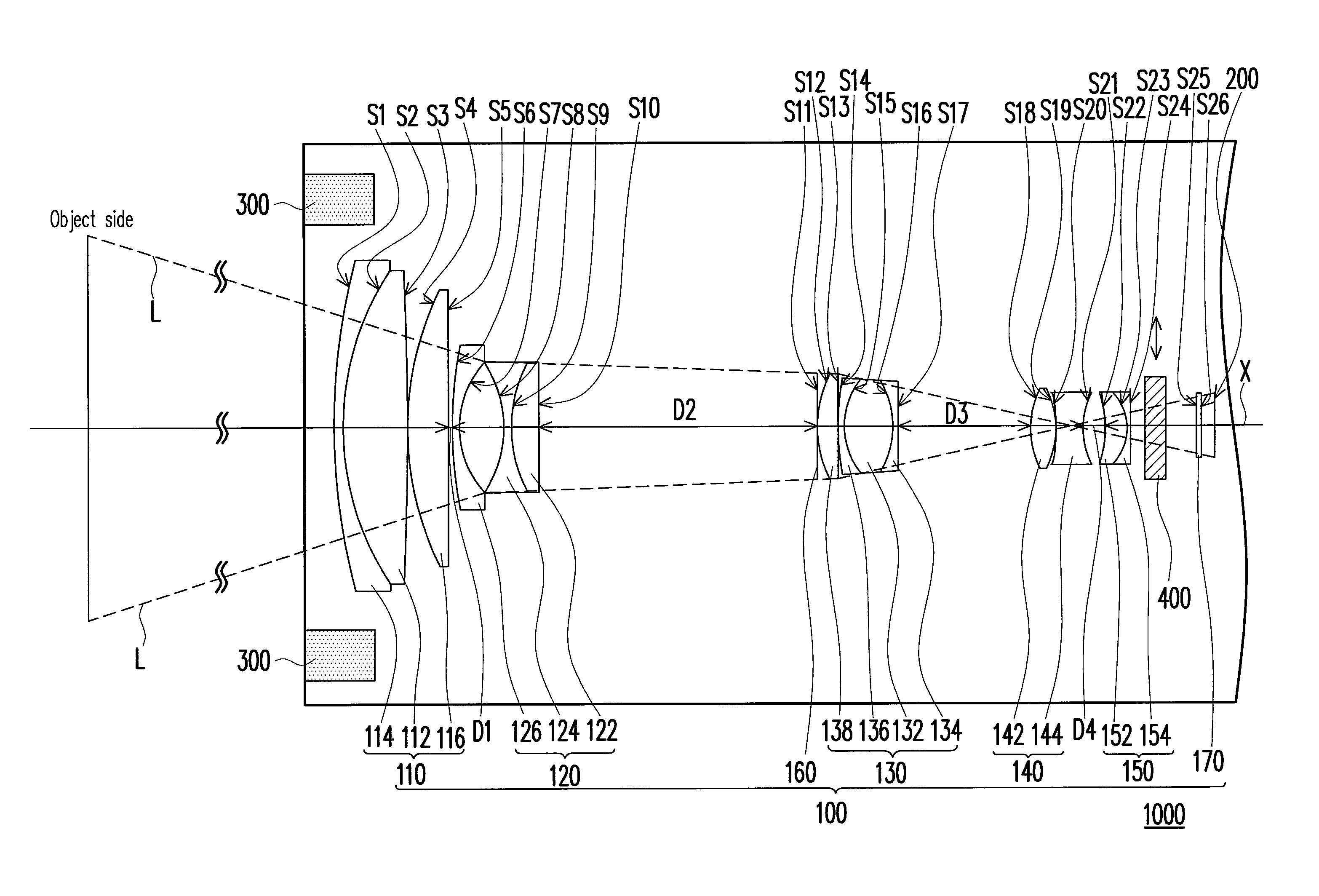
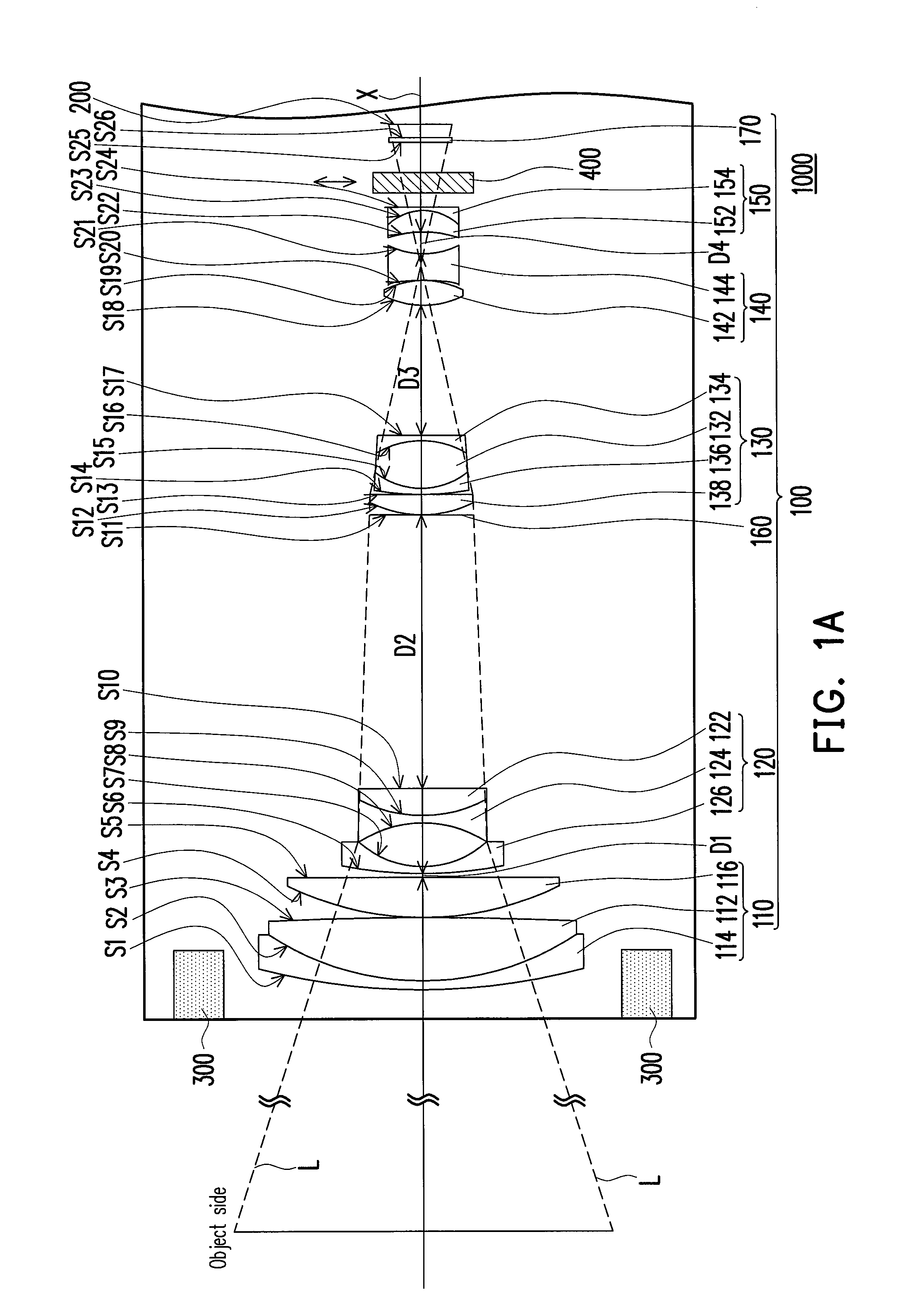
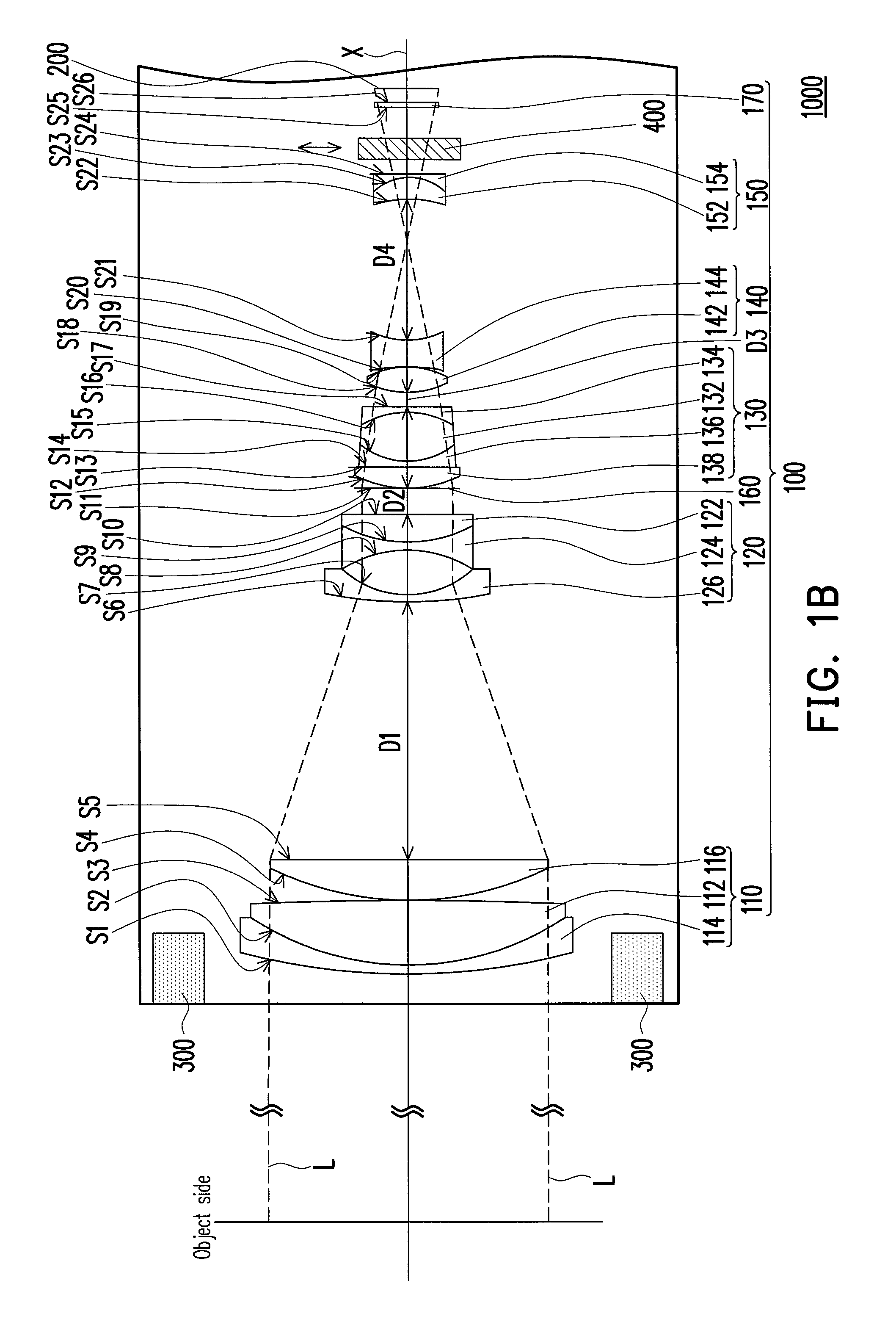
[0062]FIGS. 1A and 1B are two schematic optical structure diagrams of the image apparatus under different zoom magnifications according to the first embodiment of the invention, in which FIG. 1A illustrates the optical structure of the image apparatus at the wide-end and FIG. 1B illustrates the optical structure of the image apparatus at the tele-end. Referring to FIGS. 1A and 1B, an image apparatus 1000 of the embodiment is configured for capturing an object light-beam L from the object-side. The image apparatus 1000 of the embodiment includes a lens module 100 and a photosensitive component 200, and the lens module 100 and the photosensitive component 200 are located on the transmission path of the object light-beam L, and the lens module 100 is located between the photosensitive component 200 and the object-side. In the embodiment, the photosensitive component 200 is, for example, a charge coupled device (CCD), which the invention is not limited to. In other e...

second embodiment

The Second Embodiment

[0099]FIGS. 7A and 7B are two schematic optical structure diagrams of the image apparatus under different zoom magnifications according to the second embodiment of the invention. In particular, FIG. 7A illustrates the optical structure of the image apparatus at the wide-end and FIG. 7B illustrates the optical structure of the image apparatus at the tele-end. Referring to FIGS. 7A and 7B, the image apparatus 1000A of the embodiment is similar to the image apparatus 1000 of the first embodiment and the same components herein are notated with the same marks. The difference of the image apparatus 1000A of the embodiment from the image apparatus 1000 of the first embodiment rests in that the lens module 100A herein is somehow different from the lens module 100 in the first embodiment. In more details, the second lens group 120A, the third lens group 130A and the fourth lens group 140A are respectively from the second lens group 120, the third lens group 130 and the f...


PUM


Abstract

A lens module for capturing an object light-beam from an object-side is provided. The lens module includes a first lens group, a second lens group, a third lens group, a fourth lens group and a fifth lens group sequentially-arranged from the object-side to an image-side. The five lens groups respectively have at least one lens with positive refractive-power and at least one lens with negative refractive-power. The first, third and fifth lens groups are fixed groups, while the second and fourth lens groups are movable groups. An image apparatus including the lens module is also provided.

Description

CROSS-REFERENCE TO RELATED APPLICATION[0001]This application claims the priority benefit of Taiwan application serial no. 100146540, filed on Dec. 15, 2011. The entirety of the above-mentioned patent application is hereby incorporated by reference herein and made a part of this specification.BACKGROUND OF THE INVENTION[0002]1. Field of the Invention[0003]The invention generally relates to an optical apparatus, and more particularly, to a lens module and an image apparatus.[0004]2. Description of Related Art[0005]Along with the increasing popularity of demand on the surveillance under night and low-light environments, video cameras with 24-hours surveillance function are widespread used. In general speaking, a conventional video camera uses a light-filter for switching the 24-hours surveillance modes. In more details, when an object to be shot is under an environment with adequate luminance, a light-filter would be put down to block infrared light from entering the photosensitive com...

Claims


Application Information

Patent Timeline
Patent Type & Authority Patents(United States)
IPC IPC(8): G02B15/14G02B15/173G02B15/28
CPCG02B15/14G02B15/167G02B15/173G02B15/28G02B15/145129G02B3/04G02B9/60G02B13/18H04N7/18
Inventor WANG, KUO-CHUANLAI, SHENG-TANG
Owner YOUNG OPTICS
Why Eureka
Try Eureka