
Device for locking an opening part of a jet engine nacelle with respect to a fixed part, and nacelle equipped with such a device

a technology for locking and nacelles, which is applied in the direction of door/window fittings, keyhole guards, wing knobs, etc., can solve the problem of involving certain complexity in installing them inside the nacell

Inactive Publication Date: 2015-04-14
SAFRAN NACELLES
View PDF19 Cites 41 Cited by
  • Summary
  • Abstract
  • Description
  • Claims
  • Application Information

AI Technical Summary

Benefits of technology

[0012]By virtue of the presence of these gripping means and of the possibility of immobilizing them in the direction of movement of the opening portion, it is possible to manually move the opening portion relative to the fixed portion: it is therefore no longer necessary to provide actuation means dedicated to the movements of the opening portion, which makes it possible to save weight and complexity.
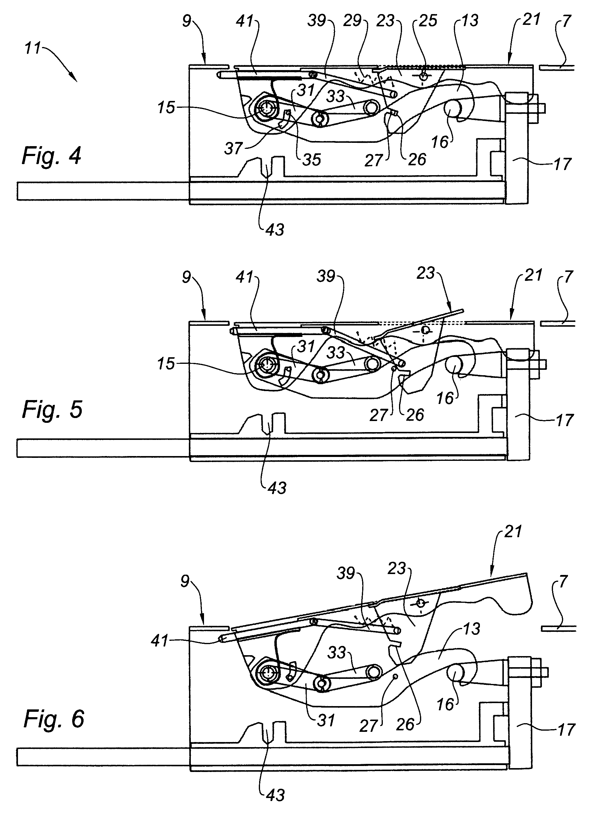
[0021]this device comprises a trigger for releasing said gripping means: this trigger makes it possible, with a slight pressure, to make the gripping means accessible,
[0022]this device comprises means for braking said opening portion relative to said fixed portion, and means for actuating these braking means, mounted on said gripping means: these braking means make it possible to prevent inadvertent movements of the opening portion during the maintenance operations,
[0024]said locking means are geographically distinct from said actuation means: this makes it possible to reconcile the respective installations of the locking means and of the actuation means with the geometric constraints of the fixed and opening portions of the nacelle.

Problems solved by technology

These specific actuation means have a not inconsiderable weight and installing them inside the nacelle involves a certain complexity.

Method used


Image

  • Device for locking an opening part of a jet engine nacelle with respect to a fixed part, and nacelle equipped with such a device
  • Device for locking an opening part of a jet engine nacelle with respect to a fixed part, and nacelle equipped with such a device
  • Device for locking an opening part of a jet engine nacelle with respect to a fixed part, and nacelle equipped with such a device

Examples


Embodiment Construction

[0034]In these figures, identical reference numbers designate identical or similar members.

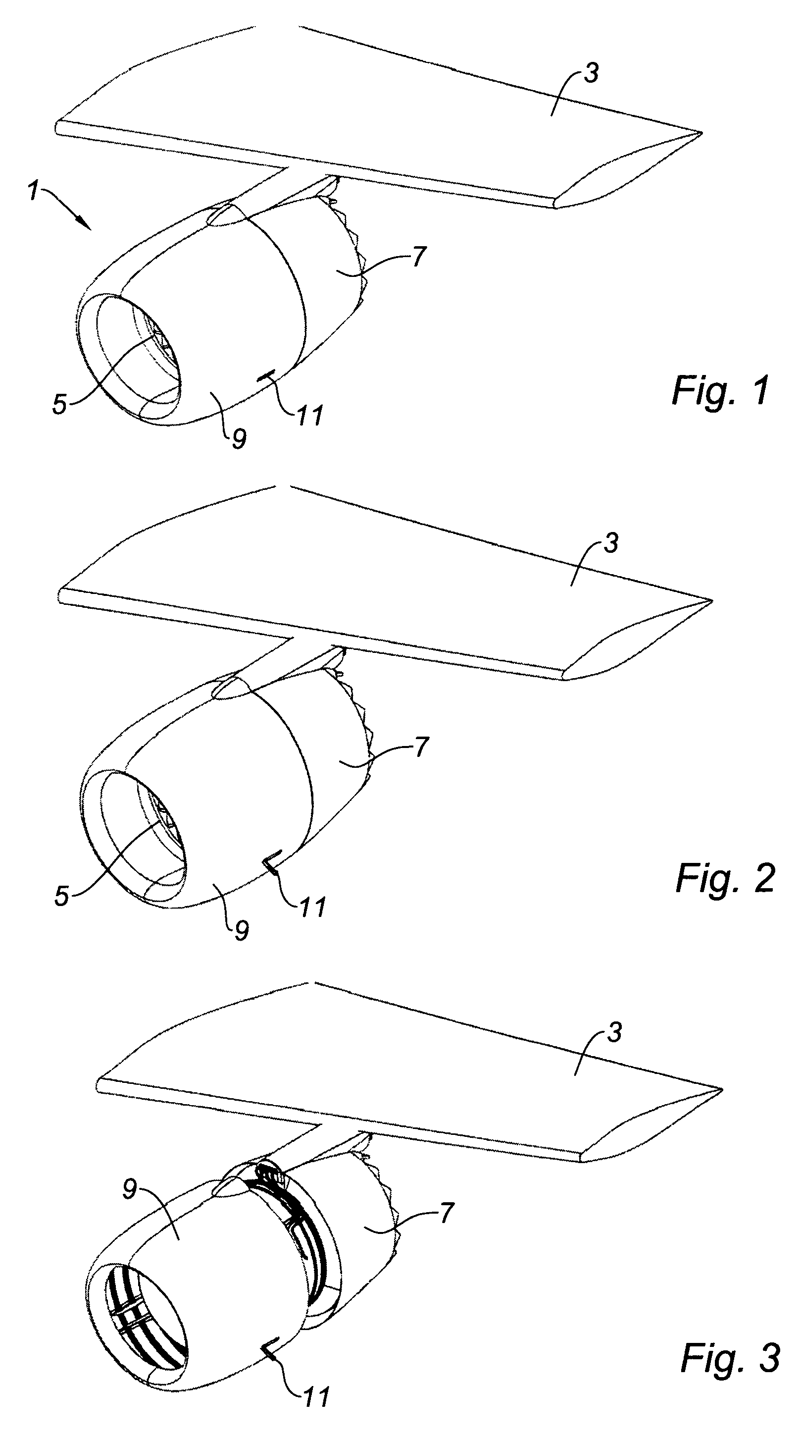
[0035]With reference to FIGS. 1 to 3, it can be seen that the nacelle 1 placed beneath an aircraft wing 3 and incorporating a turbojet 5 comprises on the one hand a rear fixed portion 7, and on the other hand a front opening portion 9 so as to allow access to the turbojet 5 for maintenance operations.

[0036]As can be seen in FIG. 3, the front portion of the nacelle 9 is opened by sliding relative to the rear fixed portion 7.

[0037]Before carrying out this sliding action, it is necessary to act on at least one locking device 11 so as to place it in an open position that can be seen in FIG. 2, making it possible to separate the front opening portion 9 from the rear fixed portion 7 of the nacelle 1.

[0038]The various ways of producing the locking device 11 will now be studied more closely. In the embodiment of FIGS. 4 to 16, this locking device comprises a hook 13 mounted so as to pivot about a spin...


PUM


Abstract

This device for locking an opening part (9) of a jet engine nacelle with respect to a fixed part (7, 17) comprises: means (13, 16) for locking said opening part (9) with respect to said fixed part (7, 17), means for actuating (21) these locking means that are mounted such that they can move on said opening part (9) between a closed position, in which they enable said locking means (13, 16) to be immobilized, and an open position, in which they enable these locking means (13, 16) to be released. Said actuating means comprise gripping means (21). This device comprises means (41, 43) for immobilizing, in the open position, said gripping means (21) with respect to said opening part (9) at least in the direction of movement of said opening part (9).

Description

TECHNICAL FIELD[0001]The present invention relates to a device for locking an opening portion of a turbojet nacelle relative to a fixed portion, and to a nacelle fitted with such a device.BRIEF DISCUSSION OF RELATED ART[0002]The prior art teaches of a system for locking an opening portion of a turbojet nacelle relative to a fixed portion, typically comprising:[0003]means for locking said opening portion relative to said fixed portion, and[0004]means for actuating these locking means, mounted so as to be able to move on said opening portion between a closed position in which they allow the immobilization of said locking means and an open position in which they allow the release of these locking means.[0005]Such a system typically makes it possible to lock together the half-cowls of a turbojet nacelle that are capable of opening upwards by pivoting about spindles substantially parallel to the spindle of the nacelle.[0006]Once these two cowls are unlocked, specific means, such as hydra...

Claims


Application Information

Patent Timeline
Patent Type & Authority Patents(United States)
IPC IPC(8): E05C19/10B64D29/06E05B1/00E05B13/00E05B17/22E05C19/14
CPCE05C19/145B64D29/06E05B1/00E05B13/00E05B17/22Y10T292/08Y10T292/0945Y10T292/1075
Inventor JORET, JEAN-PHILIPPEVAUCHEL, GUY
Owner SAFRAN NACELLES
Learn More