Method of fabricating a slip ring component

a technology of slip ring and component, which is applied in the manufacture of stator/rotor bodies, manufacturing tools, and so on

Active Publication Date: 2015-05-05
TYCO ELECTRONICS LOGISTICS AG (CH)
View PDF3 Cites 789 Cited by
  • Summary
  • Abstract
  • Description
  • Claims
  • Application Information

AI Technical Summary

Benefits of technology

[0008]Other features and advantages of the present invention will be apparent from the following more detailed description of the preferred embodiment, taken in conjunction with the accompanying drawings which illustrate, by way of example, the principles of the invention.
[0009]FIG. 1 is a perspective view of an exemplary molded interconnect device according to the disclosure with a stationary housing partially removed for clarity.
[0010]FIG. 2 is a perspective view of an exemplary molded interconnect device according to the disclosure with a stationary housing.
[0011]FIG. 3 is a perspective view of an exemplary molded interconnect device according to the disclosure with a covering on a stationary housing.
[0012]FIG. 4 is a perspective view of an exemplary slip ring component having a non-plateable shot and a plateable shot according to the disclosure.
[0013]FIG. 5 is a rotor shaft of an exemplary molded interconnect device having one slip ring component positioned and press fit onto the rotor shaft according to the disclosure.
[0014]FIG. 6 is a perspective view of an exemplary slip ring component having a non-plateable shot and a plateable shot according to the disclosure.
[0015]Wherever possible, the same reference numbers will be used throughout the drawings to represent the same parts.
[0016]Provided is an exemplary process of fabricating a slip ring component, a slip ring component, and a slip ring assembly including a slip ring component. Embodiments of the present disclosure permit signals and / or power to be transmitted from a rotating source to a controller and / or power source, utilize low and / or lower costs materials, utilize simple and / or simpler fabrication methods and / or assembly methods, and combinations thereof.

Problems solved by technology

Rotating components present challenges for electrical connectors.
For example, a rotating component directly connected through a wire to a controller becomes twisted and can break or become tangled after one or more revolutions.
Connectors having a rotor and a stator can include expensive materials and / or can be labor-intensive in fabrication.
Molding portions of the housings to form conductive paths and / or adding conductive paths can be labor intensive and, thus, add to the cost of the electrical connectors.

Method used


Image

  • Method of fabricating a slip ring component
  • Method of fabricating a slip ring component
  • Method of fabricating a slip ring component

Examples


Embodiment Construction

[0016]Provided is an exemplary process of fabricating a slip ring component, a slip ring component, and a slip ring assembly including a slip ring component. Embodiments of the present disclosure permit signals and / or power to be transmitted from a rotating source to a controller and / or power source, utilize low and / or lower costs materials, utilize simple and / or simpler fabrication methods and / or assembly methods, and combinations thereof.

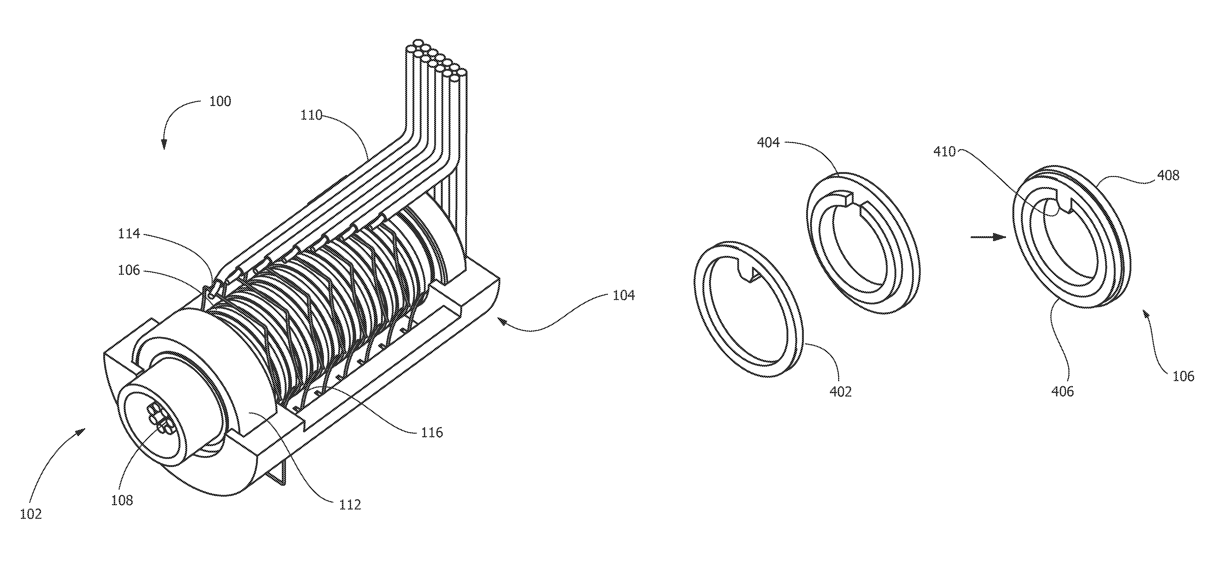
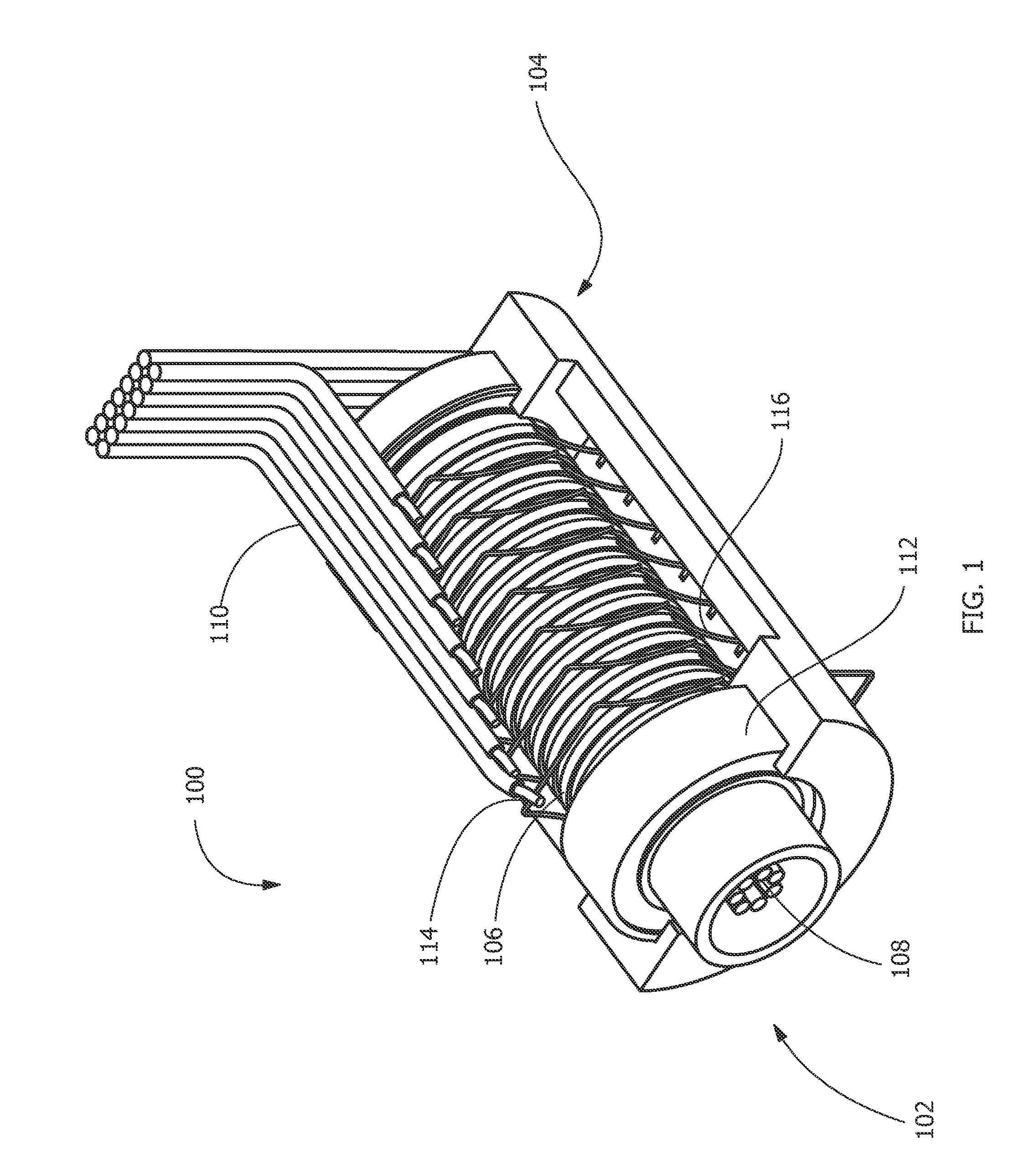
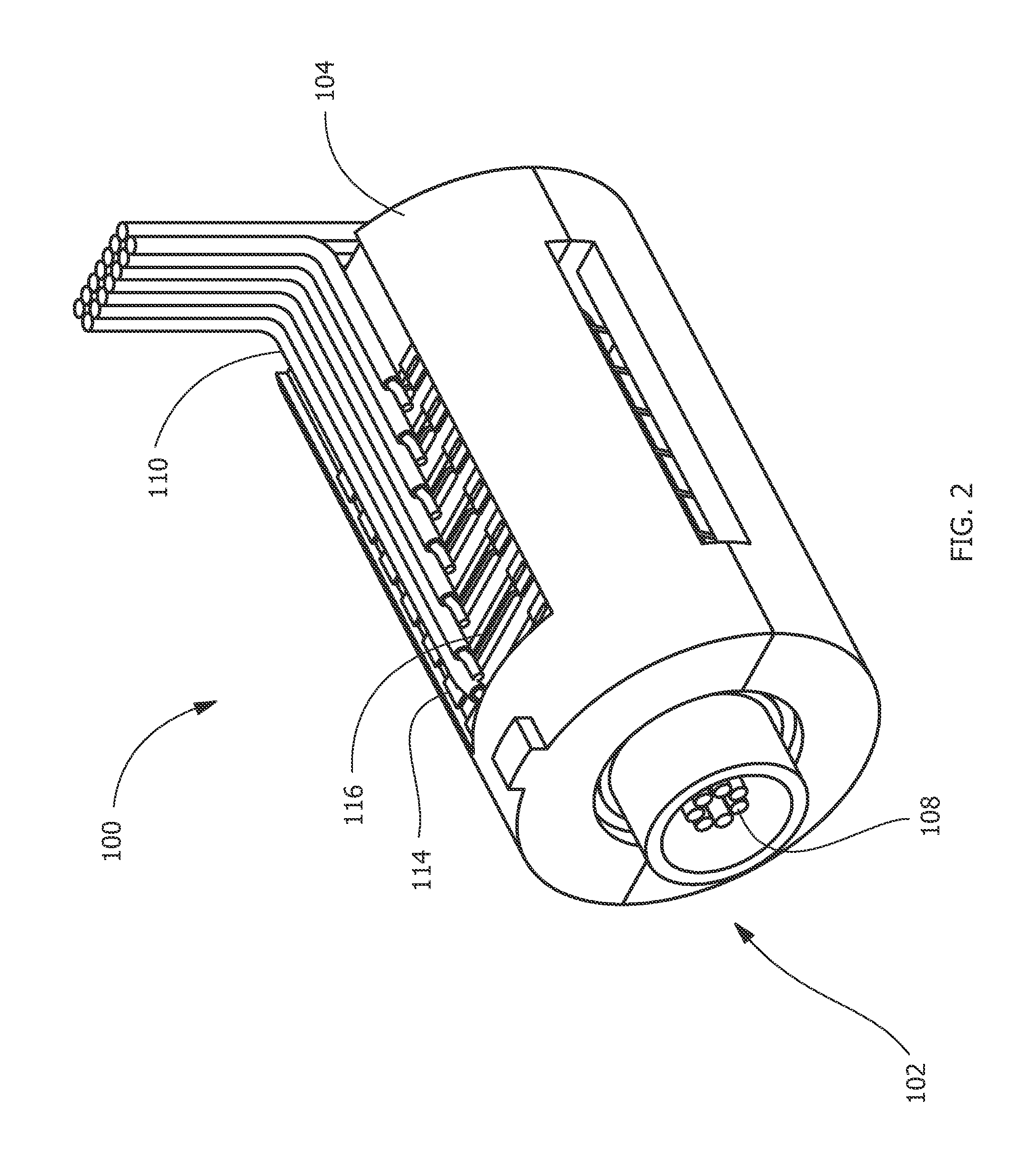
[0017]Referring to FIGS. 1 and 2, an exemplary slip ring assembly 100, for example, a molded interconnect device, includes a rotatable portion 102, a stationary housing 104, and one or more slip ring components 106 electrically connecting source wires 108 in the rotatable portion 102 to controller wires 110 in the stationary housing 104. The slip ring assembly 100 receives an electrical signal from one or more interior or the source wires 108 connected to a source (not shown), such as a camera, a rotor for a helicopter, a turbine (for example, a g...


PUM

PropertyMeasurementUnit
electrically conductiveaaaaaaaaaa
poweraaaaaaaaaa
rotationaaaaaaaaaa

Abstract

A process of fabricating a slip ring component, a slip ring component, and a slip ring assembly are disclosed. The process includes forming a first shot, forming a second shot, and immersion bathing the first shot and the second shot. The immersion bathing applies an electrically conductive plating to exposed surfaces of the second shot.

Description

FIELD OF THE INVENTION[0001]The present invention is directed to electrical connectors and components, electrical connector assemblies, and processes of fabricating electrical connectors and electrical connector assemblies. More specifically, the present invention relates to slip ring components and assemblies.BACKGROUND OF THE INVENTION[0002]Electrical connectors provide power and / or signals for various applications. Rotating components present challenges for electrical connectors. Rotating components prevent direct connection of a source to a controller and / or power source due to the rotation of the rotating component. For example, a rotating component directly connected through a wire to a controller becomes twisted and can break or become tangled after one or more revolutions. Connectors having an internal rotor and a stator can be used for such rotating components.[0003]Connectors having a rotor and a stator can include expensive materials and / or can be labor-intensive in fabri...

Claims


Application Information

Patent Timeline
Patent Type & Authority Patents(United States)
IPC IPC(8): H01R43/06H01R43/10H01R39/08H01R39/14H01R107/00
CPCH01R43/10H01R39/08H01R39/14H01R2107/00Y10T29/49009Y10T29/49011Y10T29/49012Y10T29/49204
Inventor LENKER, WILLIAM GARYGRIFFITH, GREGORY GORDONHOWARD, EDWARD JOHN
Owner TYCO ELECTRONICS LOGISTICS AG (CH)
Why Eureka
Try Eureka