
Projection display device

a technology of projection display and display device, which is applied in the direction of color television details, television systems, instruments, etc., can solve the problem of not having an optimum white balance, and achieve the effect of optimum white balance, color reproducibility range and white balan

Active Publication Date: 2015-05-05
SHARP NEC DISPLAY SOLUTIONS LTD
View PDF17 Cites 10 Cited by
  • Summary
  • Abstract
  • Description
  • Claims
  • Application Information

AI Technical Summary

Benefits of technology

[0038]According to the present invention, even if the brightness of each of the light-emitting elements in the respective colors varies due to temperature or aging, since the intensities of the lights emitted from the light-emitting elements are monitored, the amount-of-light controller can change the driving conditions for the red color light, the green color light, and the blue color light to achieve the optimum white balance. Consequently, the projection display device offers the following advantages:
[0039]1) Even if the brightness of each of the light-emitting elements in the respective colors varies due to changes in the junction temperature, the individual light-emitting device specificity, aging of the light-emitting element, and driving conditions therefore, a white balance and color reproducibility range can be maintained.
[0040]2) Chromaticity coordinates of the white color and chromaticity coordinates of the three primaries can be brought to match given video standards.
[0041]3) Displayed images can be brightened or darkened for electric power saving while maintaining a white balance and a color reproducibility range depending on the video signal.

Problems solved by technology

For the above reasons, light emission efficiency that varies due to a change in the junction temperature and a change in the brightness of a light-emitting element due to aging is different depending on the color of the emitted light, so that the white balance based on the three primaries of the displayed image varies, and it is impossible to maintain images having an optimum white balance.

Method used


Image

  • Projection display device
  • Projection display device
  • Projection display device

Examples


Embodiment Construction

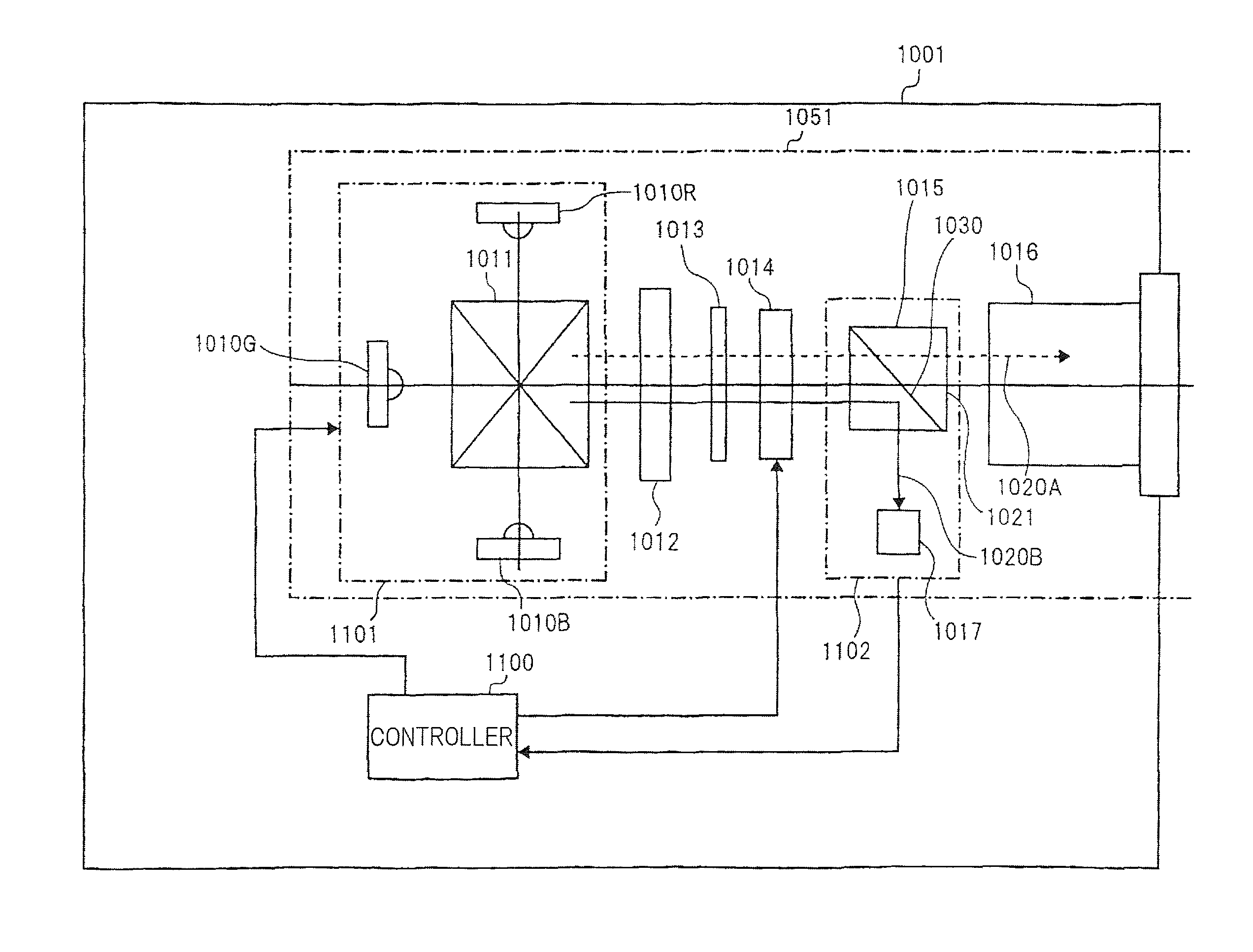
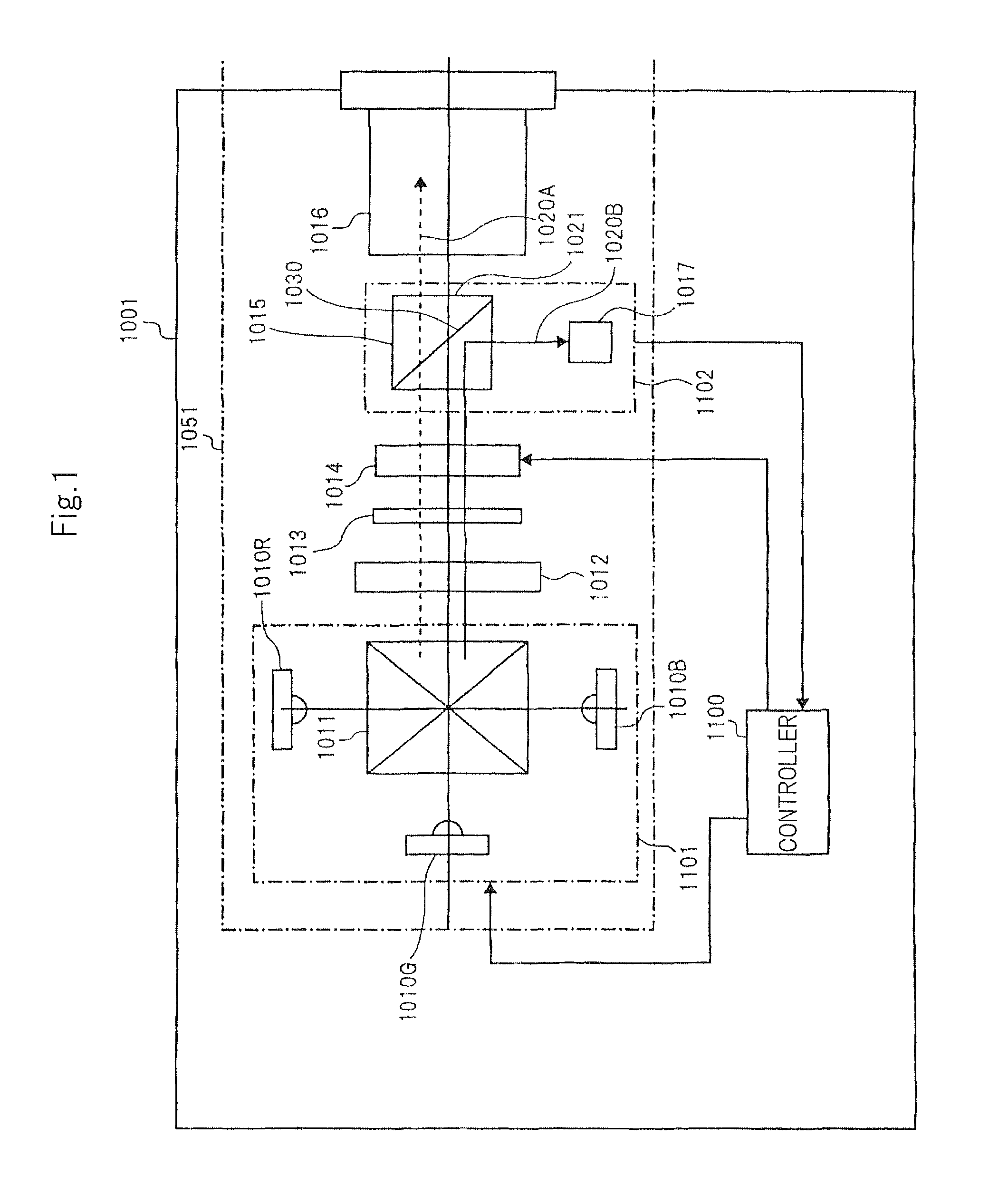
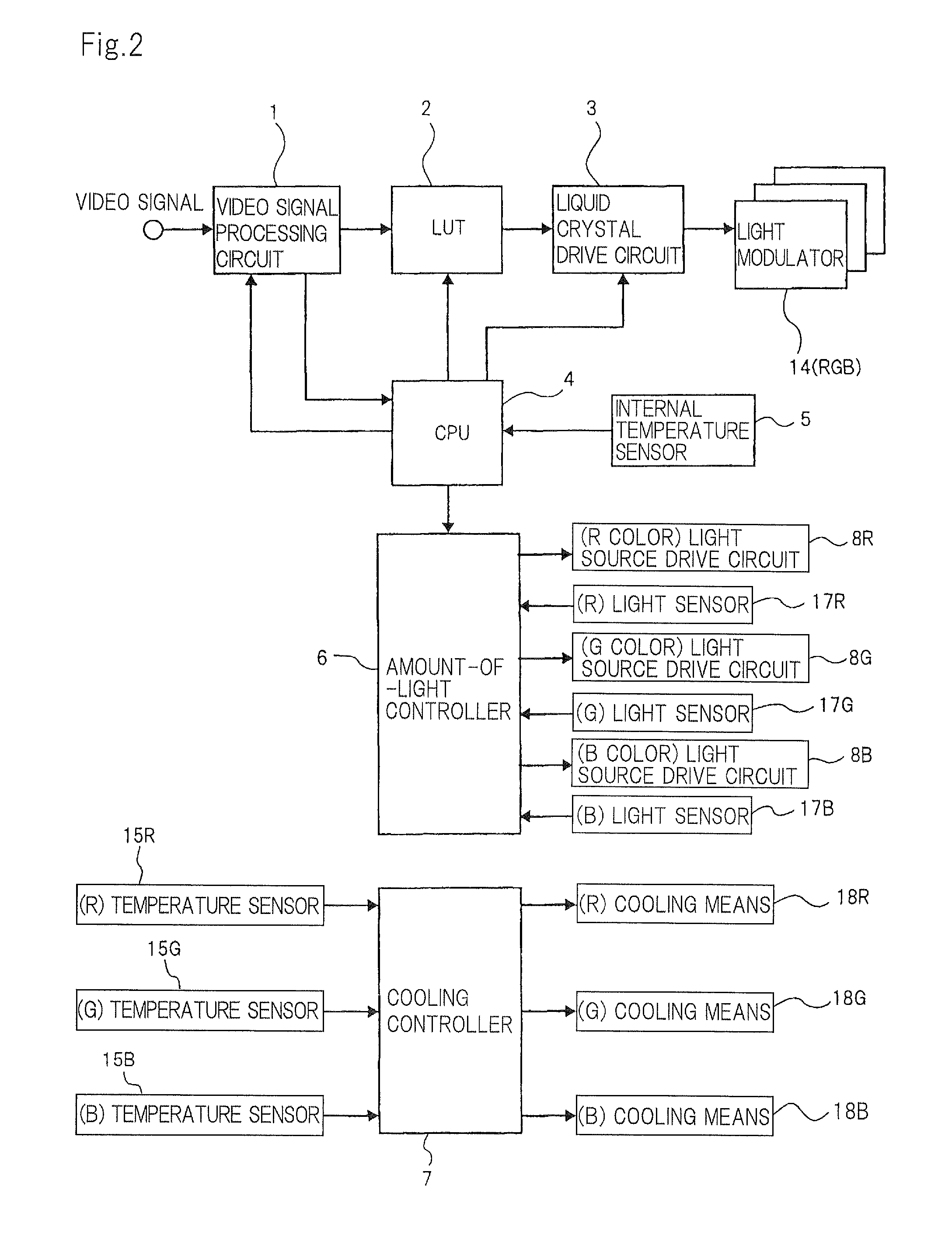
[0048]A projection display device according to the present invention comprises a light source including light-emitting elements for emitting lights in colors of red, green, and blue, light modulators including liquid crystal devices, light sensors, an amount-of-light controller, and a light source cooling means. The light sensors detect respective amounts of lights emitted from the respective light-emitting elements, and the amount-of-light controller compares and adjusts the amounts of lights from the light-emitting elements in the respective colors of red, green, and blue to keep a white balance based on the colors. The projection display device maintains displayed images with an optimum white balance even when the junction temperatures of the light-emitting elements vary and even when the light-emitting elements are deteriorated due to long-term use, resulting in a reduction in the amounts of emitted lights. The white balance means the ratio (balance) of the amounts of lights emi...


PUM


Abstract

A projection display device includes light sources having light-emitting elements for emitting lights in R, G, B colors, temperature sensors for the respective colors disposed near the light sources in the respective colors, light sensors for the respective colors disposed near the light sources in the respective colors for detecting light leakages from the light sources in the respective colors, a cooling unit for cooling the light sources in the respective colors, light modulators employing three panels of liquid crystal devices, a projection optical system, an amount-of-light controller for maintaining a predetermined ratio of the amounts of lights emitted from the light sources in the respective colors, and a cooling controller for controlling the cooling unit for the light sources in the respective colors.

Description

TECHNICAL FIELD[0001]The present invention relates to a projection display device, and more particularly to a projection display device which adjusts the amount of light to an amount-of-light ratio for a desired white balance using light-emitting elements.BACKGROUND ART[0002]Projection display devices are known as display devices for the user to enjoy video and images on a large screen. Projection display devices of the background art mainly achieve an enlarged-scale display according to the following procedure:[0003]White color from a light source is separated into red light, green light, and blue light by a color separating means, and the separated monochromatic lights are modulated by a light modulator such as a liquid crystal device or a DMD.[0004]The modulated images in the respective hues are combined to generate a color image by a color combining means such as a cross dichroic prism.[0005]The generated color image is displayed at an enlarged scale on a screen or the like by a...

Claims


Application Information

Patent Timeline
Patent Type & Authority Patents(United States)
IPC IPC(8): G03B21/20G03B21/16G09G3/00G09G3/34
CPCG03B21/16G03B21/2053G09G3/3413G09G2320/041G09G2360/145G09G3/002G09G2320/0242G09G2320/064G09G2320/0646G09G2330/06G09G2360/16G03B21/2033H04N9/3155
Inventor NAKANISHI, SHUICHI
Owner SHARP NEC DISPLAY SOLUTIONS LTD
Learn More