AI technical title is built by PatSnap AI team. It summarizes the technical point description of the patent document.
a technology of optoelectronic devices and complexes, which is applied in the direction of triarylamine dyes, sustainable manufacturing/processing, and final product manufacturing, etc., can solve the problems of unfavorable ohmic loss, increased charge carrier streams, and increased cost of noble metals
Active Publication Date: 2015-05-05
SAMSUNG DISPLAY CO LTD
View PDF6 Cites 2 Cited by
Summary
Abstract
Description
Claims
Application Information
AI Technical Summary
This helps you quickly interpret patents by identifying the three key elements:
Problems solved by technology
Method used
Benefits of technology
Benefits of technology
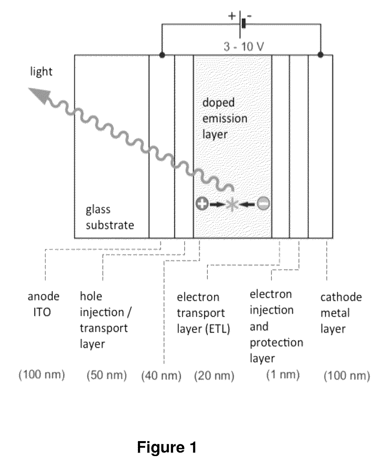
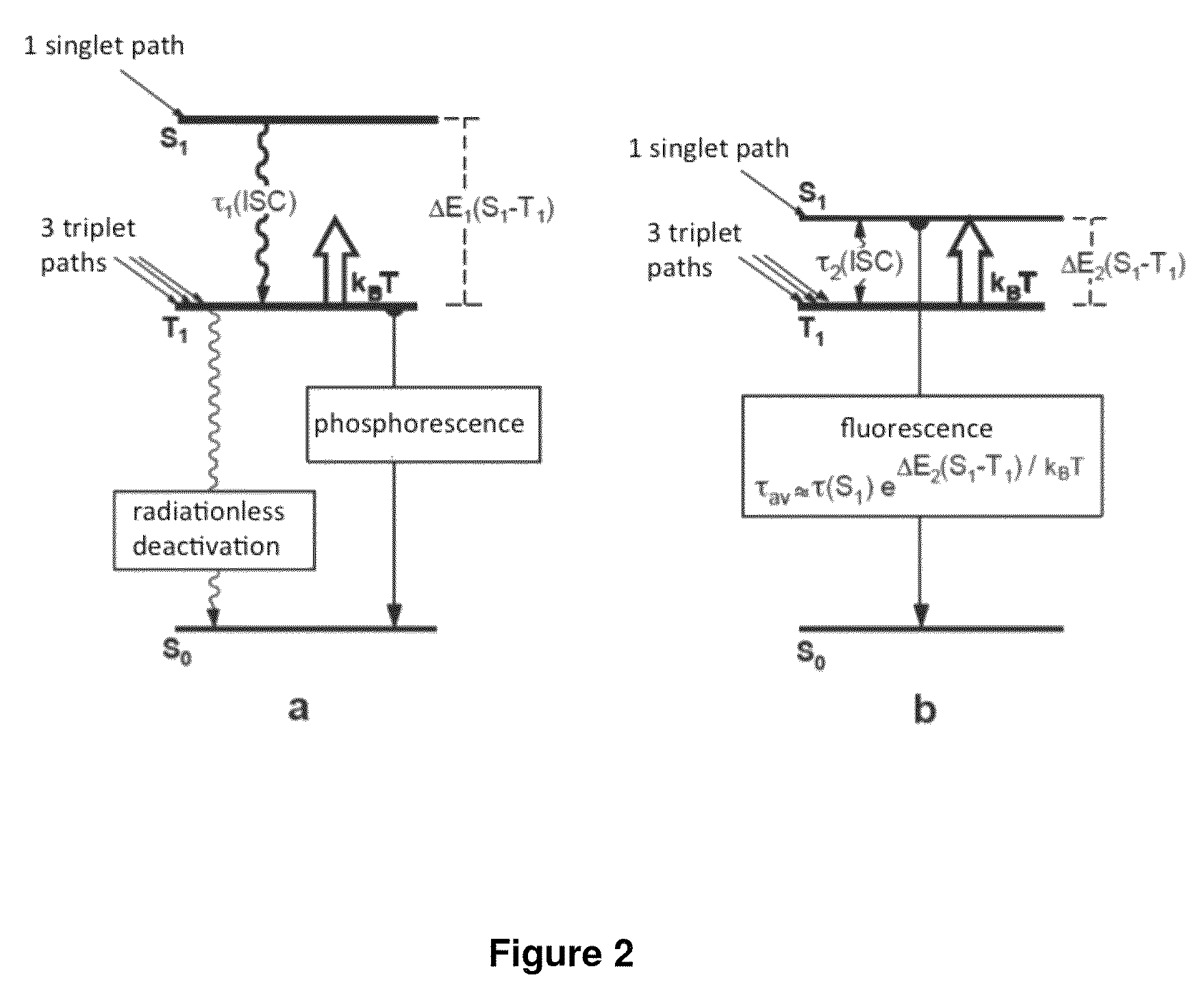
[0028]It is of particular importance to loosen the forbidden transition prohibition from the excited triplet state T1 to the singlet state S0 in order to develop emitter molecules with shortest possible emission decay times, yet high emission quantum yields. OLEDs using such emitters show a markedly diminished roll-off behavior of efficiency and provide for a longer operating life of the optoelectronic device.
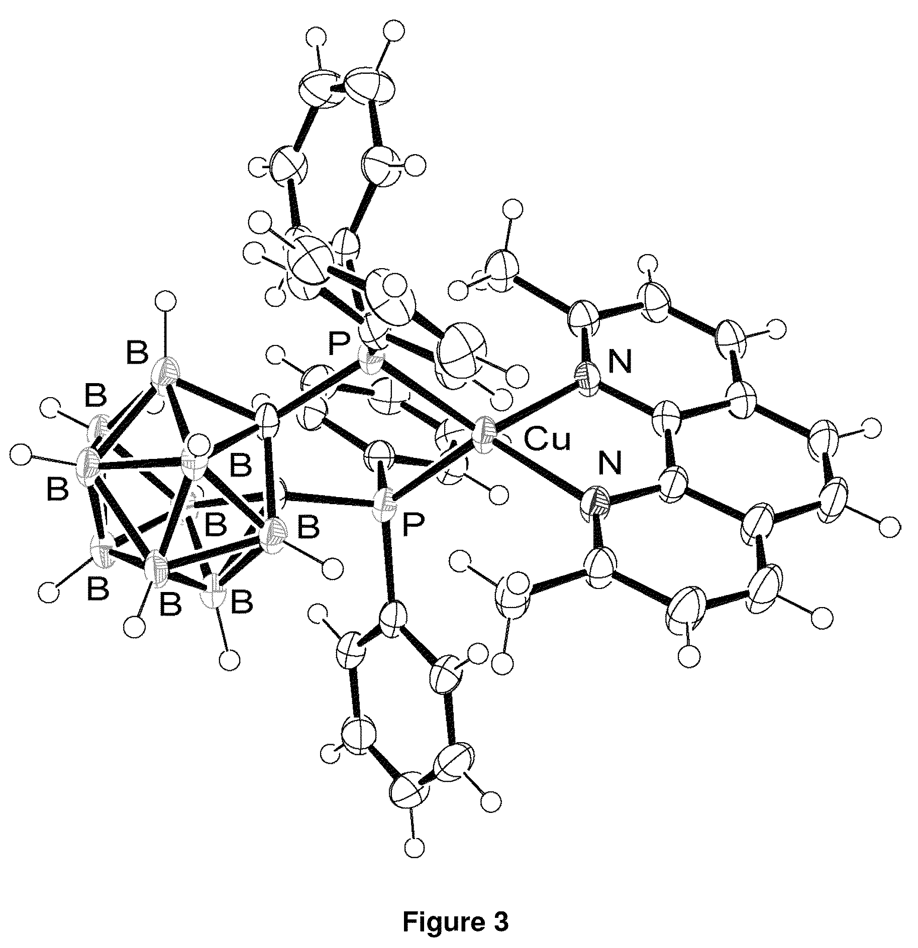
[0051]When transitioning into an electronic excited state with pronounced metal-to-ligand charge-transfer character, the metal atom is formally oxidized to Cu(II), and a relevant change of the geometry towards a quadratic-planar coordination occurs, which can be called a “planarization” of the complex. This process provides for a very effective mechanism for quenching luminescence.
[0052]In the copper(I) complexes of the invention, this quenching mechanism is prevented or strongly reduced by the presence of a sterically demanding substituent at the diimine ligand N∩N (in particular in positions 2 and 9 of 1,10-phenanthroline or in positions 3 and 3′ of 2,2′-bipyridine) by a hindrance of change of geometry at the Cu atom. At the same time, such substitutions help prevent nucleophilic reactions with the Cu center (with solvents, contaminants, easily coordinating matrix material). Already a methyl group leads to a stiffening of the resulting Cu complexes. A sterically demanding substituent therefore is, besides methyl, an alky group —(CH2)n—CH3 (n=0-20) (also branched), an aryl group with 6-20 carbon atoms (e.g. -Ph), alkoxy groups —O—(CH2)n—CH3 (n=0-20), an aryloxy group (e.g. —OPh) or a silane group (e.g. —SiMe3). The alkyl and aryl groups can also be substituted (e.g. with halogens, alkoxy or silane groups, etc.) or lead to annelated ring systems (see example 2).Chemical Lead
[0088]For the hole conductors, generally the analogous applies as for the electron conductor. The attachment of the hole conductor to the diimine ligand can most conveniently be realized through palladium-catalyzed coupling reactions; further attachments, also via a bridge, are also possible.
Problems solved by technology
This predominantly involves very expensive noble metals such as iridium, platinum or else gold.
Moreover, a large number of OLED emitter materials known to date are ecologically problematic, so that the use of less toxic materials is desirable, such as copper(I) complexes.
Consequently, further charge carrier streams can no longer lead completely to the occupation of the excited and emitting states.
The result is then unwanted ohmic losses.
This leads to a distinct decline in efficiency of the OLED device with rising current density (called “roll-off” behavior).
For instance, disadvantages are found particularly in the case of use of emitters with long emission lifetimes for OLED illuminations where a high luminance, for example of more than 1000 cd / m2, is required (cf.
Furthermore, molecules in electronically excited states are frequently more chemically reactive than in ground states so that the likelihood of unwanted chemical reactions increases with the length of the emission lifetime.
The occurrence of such unwanted chemical reactions has a negative effect on the lifetime of the device.
Furthermore, Cu(I)-complexes undergo strong geometry changes after the excitation (through electron-hole recombination or through optical excitation) which leads to the reduction of emission quantum yields.
Also, the emission colors are shifted due to these processed towards red, which is unwanted.
Moreover, many of the known copper-complexes are not soluble in the solvents that are needed for technical use.
This is another aspect why the use of such complexes is disfavored.
Method used
Image
Click on the blue label to locate the original text in one second.
Reading with bidirectional positioning of images and text.
Examples
example 1
1,10-Phenanthroline ligands that increase solubility in nonpolar solvents
[0121]4,7-dichloro-2,9-dimethyl-1,10-phenanthroline, Phen1, is synthesized according to the literature (M. Schmittel, H. Ammon Eur. J. Org. Chem. 1998, 785.). For the substitution with a n-butyl group, an equimolar amount of n-HexMgBr and CuBr is added. The purification of Phen2 is done using column chromatography over silica gel.
[0123]The phenanthroline-dichloride Phen3 is synthesized according to (M. Schmittel, H Ammon Eur. J. Org. Chem. 1998, 785.). The synthesis of Phen4 is performed analogously to Phen2.
[0125]2,4,7,9-tetra-methyl-1,10-phenanthroline, Phen5, is synthesized according to (G. Butt, R. D. Topsom, J. Heterocyclic Chem. 1981, 18, 641). 2,4,7,9-Tetrabromomethylen-1,10-phenanthroline, Phen6, is synthesized via side chain bromation using NBS and isolated by column chromatography (SiO2). The reaction with n-HexLi leads to Phen7.
[0126]
PUM
Property
Measurement
Unit
emission decay time
aaaaa
aaaaa
emission life time
aaaaa
aaaaa
thickness
aaaaa
aaaaa
Abstract
The invention relates to neutral mononuclear copper (I) complexes for emitting light and with a structure according to formula (A) in which: M represents: Cu(I); L∩L represents: a single, negatively charged, bidentate ligand; N∩N represents: a diimine ligand (substituted with R and FG), in particular a substituted 2,2′-bipyridine derivative (bpy) or a substituted 1,10-phenanthroline derivative (phen); R represents: at least one sterically demanding substituent for preventing the planarization of the complex in the excited state; FG=functional group, and represents: at least one second substituent for increasing solubility in organic solvents. The substituent can also be used for electron transport or alternatively for hole transport, said functional group being bound to the diimine ligands either directly or by means of suitable bridges; and the copper (I) complex: having a ΔE(S1−T1) value of less than 2500 cm−1 between the lowest excited singlet state (S1) and the triplet state (T1) which lies below; having an emission lifespan of at most 20 μs; having an emission quantum yield of greater than 40%, and a solubility of at least 1 g / L in organic solvents, in particular polar organic hydrocarbons such as acetone, methyl ethyl ketone, benzene, toluene, chlorobenzene, dichlorobenzene, dichloromethane, chloroform, dichloroethane, tetrachloroethylene, alcohols, acetonitrile or water.
Description
CROSS-REFERENCE TO RELATED APPLICATIONS[0001]This application is a national stage application under 35 U.S.C. §371 of PCT Application No. PCT / EP2011 / 062491, filed Jul. 20, 2011, which claims priority to and the benefit of German Application No. DE 10 2010 031 831.0, filed Jul. 20, 2010, which is incorporated herein by reference in its entirety.[0002]The present invention relates to the use of soluble copper(I) complexes (Cu(I)-complexes) as emitters in OLEDs (organic light-emitting diodes) and in other optoelectronic devices.INTRODUCTION[0003]A dramatic change is currently on the horizon in the field of visual display and illumination technology. It will be possible to manufacture flat displays or illuminated surfaces having a thickness of less than 0.5 mm. These are notable for many fascinating properties. For example, it will be possible to achieve illuminated surfaces in the form of wallpaper with very low energy consumption. It is also of particular interest that color visual di...
Claims
Application Information
Patent Timeline
Application Date:The date an application was filed.
Publication Date:The date a patent or application was officially published.
First Publication Date:The earliest publication date of a patent with the same application number.
Issue Date:Publication date of the patent grant document.
PCT Entry Date:The Entry date of PCT National Phase.
Estimated Expiry Date:The statutory expiry date of a patent right according to the Patent Law, and it is the longest term of protection that the patent right can achieve without the termination of the patent right due to other reasons(Term extension factor has been taken into account ).
Invalid Date:Actual expiry date is based on effective date or publication date of legal transaction data of invalid patent.

