
Planing hull for rough seas

a rough sea and planing technology, applied in the field of watercraft hulls, can solve the problems of poor seakeeping, lack of seakindliness and directional stability, and watercraft with exclusively flat planing surfaces cannot achieve high seakeeping and seakindliness, so as to improve seakeeping and seakindliness

Active Publication Date: 2015-05-26
HULL SCI RES LLC
View PDF68 Cites 11 Cited by
  • Summary
  • Abstract
  • Description
  • Claims
  • Application Information

AI Technical Summary

Benefits of technology

[0016]It is an object of this invention to provide a novel watercraft planing hull with improved seakeeping and seakindliness (in rough seas), seaworthiness, stability, planing efficiency, and payload capacity.
[0017]It is also an object of this invention to improve boat handling by providing a planing hull that produces fully banked turns and eliminates heeling and chine walking.
[0018]It is another object of the invention to provide a watercraft hull that will operate with substantially lower slamming than a conventional deep-V hull, especially when the hull hits the water surface heeled to a side when the hull is not symmetrically upright.

Problems solved by technology

However, conventional wisdom is that a watercraft with exclusively flat planing surfaces cannot achieve high seakeeping and seakindliness in rough seas.
Watercraft with a relatively flat or shallow V planing hull bottom, as measured relative to the horizontal, have efficient planing lift and are very stable, but have very poor seakeeping in rough seas, i.e., they also lack seakindliness and directional stability in rough seas.
Despite the improvements found with the deep V hull design, planing boats can provide uncomfortable rides.
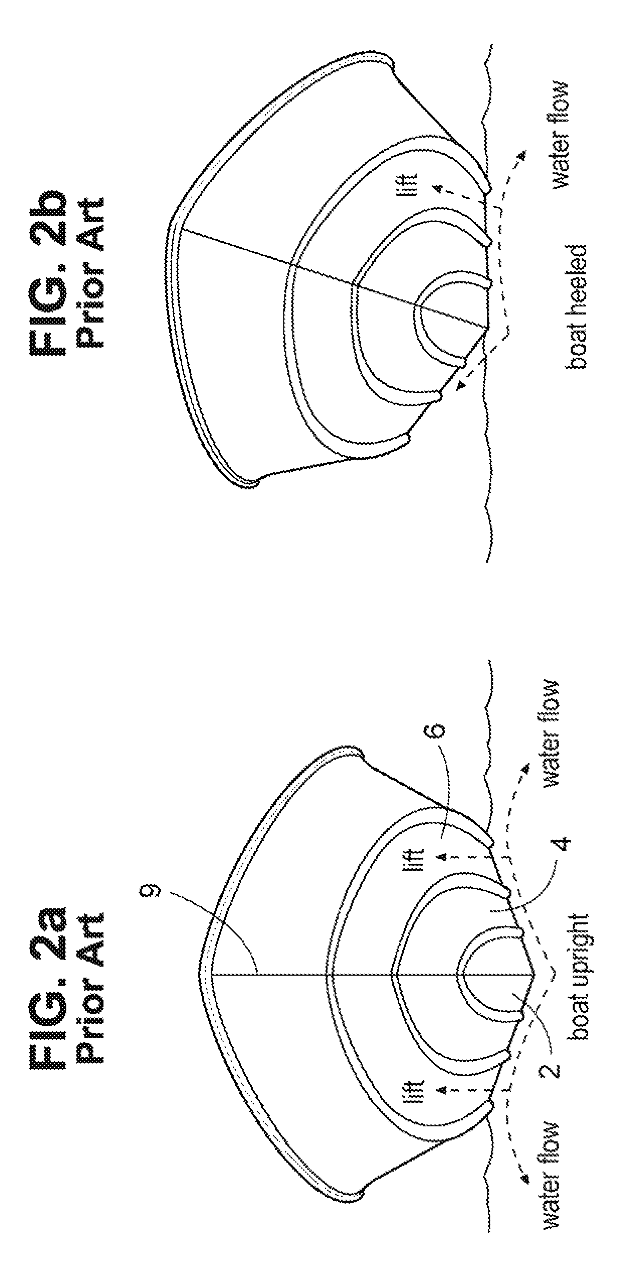
Maintaining a conventional planing hull upright however is difficult to achieve since the deep-V hull is characteristically soft in roll and will heel in response to any asymmetric load such as weight shift, propeller torque, cross wind and waves.
A dynamic system may be added to control the boat attitude; however, this adds complexity and cost.
When a deep-V boat heels to either side, its effective deadrise is decreased by the heel angle such that it loses the low slamming benefits of a deep-V hull.
A particularly dangerous condition in which to have excessive roll is when turning in rough seas from a head to a quartering to a beam sea.
Heeling over during this maneuver causes excessive pounding and uncomfortable to dangerous levels of roll.
However, it appears that several problems must be resolved before a planing monohull with an extremely high deadrise can be successfully reduced to practice.
For example, an extremely deep V hull has greater stability problems than a deep V being even more tender in roll.
Further, although the orientation of its surfaces relative to the water improves its seakeeping and seakindliness, an extremely deep V hull also produces far less dynamic lift than a flatter hull.
The inadequate planing lift of a deeper V makes getting over critical speed, also called hump speed, more difficult, reduces the payload capacity, and increases operating draft.
In addition, the limited hull width of an extremely deep V restricts arrangements and has low internal volume.
The hull can have sufficient vertically arranged and increasing buoyant volume to provide progressive lift to counter hull plunging motions when transiting through wave troughs; however, conventional wisdom on these vessels is that a watercraft with ultra high deadrise panels cannot achieve high lift and planing efficiencies.
Finally, monohulls, with higher fineness ratios, improve seakeeping of watercraft but can have static and dynamic stability issues as well as non-optimal running trims.
However, conventional wisdom is that a narrow planing hull is not as efficient as a wider hull and cannot carry as heavy loads.

Method used


Image

  • Planing hull for rough seas
  • Planing hull for rough seas
  • Planing hull for rough seas

Examples


Embodiment Construction

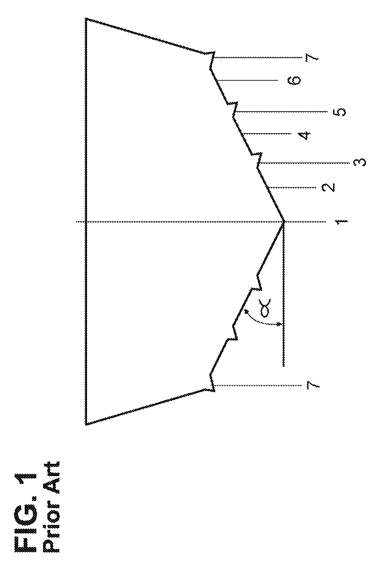
[0063]Referring now to the drawings in detail, FIG. 1 shows the transverse cross-section, at the transom, of a conventional deep-V hull. The hull has a V shaped bottom, including a conventional narrow keel 1, a plurality of (in this case three) pairs of flat panels 2, 4, and 6, separated by longitudinal strakes 3 and 5, and flat chines 7. The strakes are typically narrow wedge shaped elements with reverse deadrise primarily intended to separate water spray from the hull. The deadrise angle α for all the flat panels 2, 4 and 6 of the hull at the aft end or transom 8 is generally between 20 and 30 degrees. Typically, such hull panels increase in deadrise moving forward to a deadrise of about 43 degrees or slightly higher to provide a bow entry to slice through waves rather than slamming into them. The hull also includes a conventional curved bow 9 (see FIG. 2a), a forebody section, and a forefoot.

[0064]As noted above, contemporary deep V hulls possess relatively good seakeeping charac...


PUM


Abstract

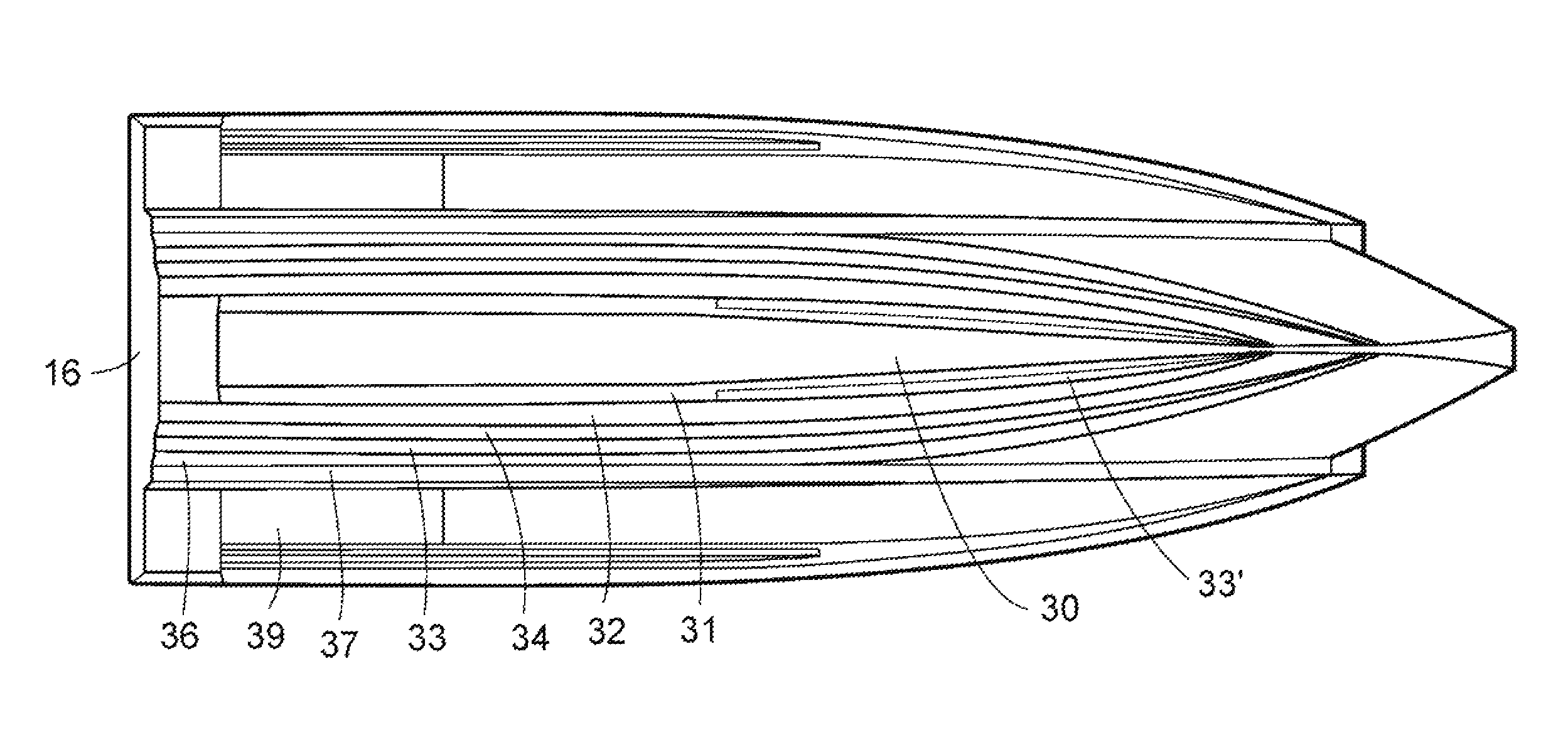
The disclosed watercraft hull has a flat pad keel whose width tapers towards the bow and its width at the transom is 15% to 25% of the hull's width at its chines. The hull is symmetric about its centerline, has a fine entry bow, a transom, and a pair of hard chines. Between the pad keel and the chines the hull has at least one pair of generally flat panels referred to herein as longitudinal steps having approximately 0 degrees of deadrize forming planing surfaces symmetrically located about the hull centerline. The hull also includes at least one pair of ultra high deadrize panels, outboard of and adjacent to the pad keel, located symmetrically about the hull centerline, and extending therefrom to the flat planing panels above them. The ultra high deadrize panels have a minimum average deadrize of approximately 50 degrees measured along their length. Additional flat planing surface structures having approximately 0° deadrize may be installed longitudinally on the hull between the pad keel and the hard chine such that the vertical offset between any two planing surfaces along the hull's stagnation line does not exceed approximately six inches. High deadrize panels or fillet panels with deadrize angles of between about 0.20 and 35 degrees may be included in the hull outboard of and adjacent to the ultra high deadrize panels and located symmetrically about the hull centerline. The fillet panels are tapered into wedge shapes at their forward ends to blend into the adjacent ultra high deadrize and flat planing panels.

Description

[0001]This application claims the benefit of U.S. Provisional Application No. 61 / 439,105 filed Feb. 3, 2011 and U.S. patent application Ser. No. 13 / 231,238 filed Sep. 13, 2011; the disclosures of both which are incorporated herein by reference.[0002]This application is a continuation-in-part of U.S. patent application Ser. No. 13 / 231,238.TECHNICAL FIELD[0003]The present invention relates to a watercraft, and particularly, to a watercraft hull having a very high deadrise central planing hull portion including longitudinal flat planing steps or panels.BACKGROUND OF THE INVENTION[0004]Watercraft which are designed to operate in the planing mode are well known. Empirical evidence based on naval architecture and hydro-dynamic research, testing and experimentation has established beneficial performance attributes from three important features of such watercraft.[0005]First, flat bottom planing hull surfaces with 0 degree deadrise angles are known to achieve the most efficient planing lift...

Claims


Application Information

Patent Timeline
Patent Type & Authority Patents(United States)
IPC IPC(8): B63B1/32B63B1/04
CPCB63B1/042B63B1/20B63B2001/186B63B2001/201B63B2001/202
Inventor LOUI, STEVEN C. H.PARISH, MEALANIYAMASHITA, SCOTT
Owner HULL SCI RES LLC
Learn More