
Method of generating view-dependent compensated images

a compensation image and image technology, applied in the field of image projectors, can solve the problems of distortion of the projected image, inability to achieve the ideal projection surface characteristics, and inability to compensate for the image, so as to achieve the effect of expanding the capability of the procam system and avoiding overcompensation

Active Publication Date: 2015-06-02
NAT TAIWAN UNIV +1
View PDF5 Cites 0 Cited by
  • Summary
  • Abstract
  • Description
  • Claims
  • Application Information

AI Technical Summary

Benefits of technology

The present invention provides a method for generating view-dependent compensated images for non-Lambertian surfaces using a single camera and projector. The method predicts calibration images for different viewing angles and introduces a feedback to re-estimate the specular light iteratively, which avoids over-compensation. The technical effects of the invention are a simplified scheme, improved capability of a procam system, and avoidance of over-compensation.

Problems solved by technology

In practice, however, the projection surface available in the surroundings is often far from ideal and causes distortions to the projected image.
As a result, compensation must be applied to the image before projection to counteract the non-ideal characteristics of the projection surface.

Method used


Image

  • Method of generating view-dependent compensated images
  • Method of generating view-dependent compensated images
  • Method of generating view-dependent compensated images

Examples


Embodiment Construction

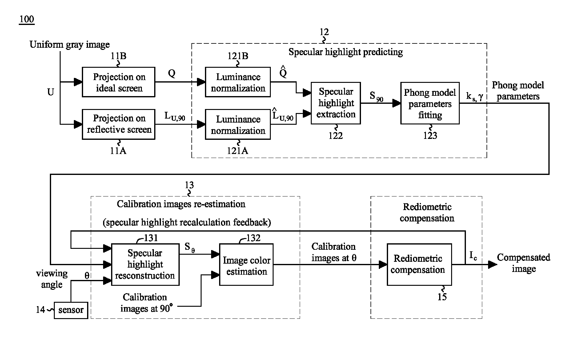
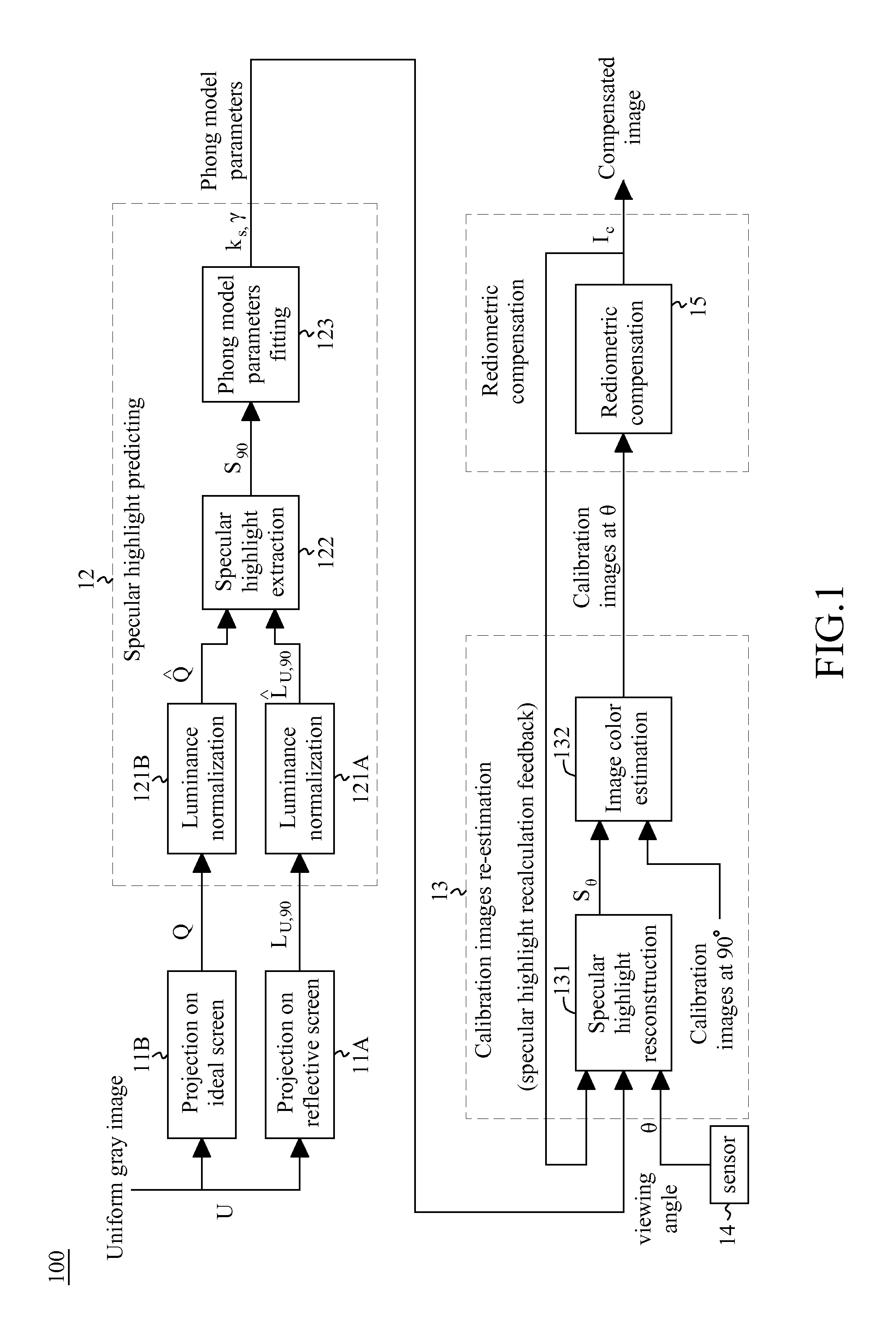
[0013]FIG. 1 shows a block diagram illustrative of architecture 100 of generating view-dependent compensated images for a non-Lambertian (or reflective) surface according to one embodiment of the present invention. The composing blocks of FIG. 1 may be implemented by hardware or be performed, for example, by a digital signal processor.

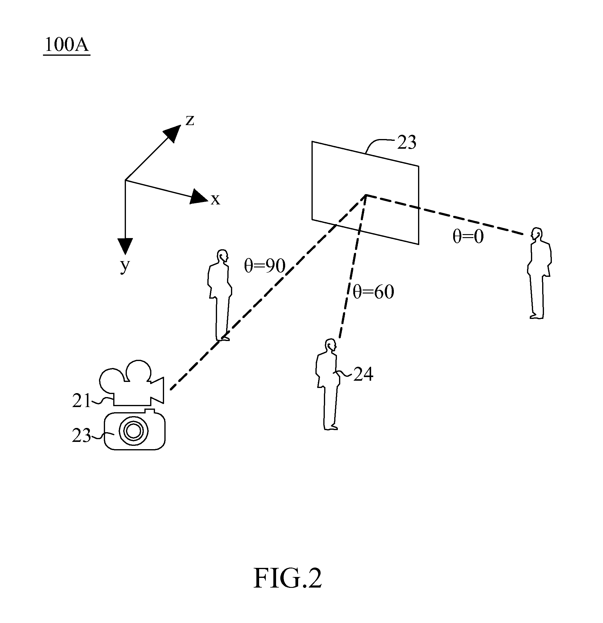
[0014]FIG. 2 shows an exemplary embodiment, to which a projector-camera (procam) system 100A comprised of a projector 21 and a camera 22 bound together may be adapted. However, the embodiment, with minor modification, may also be adaptable to a procam system comprised of multiple projectors and cameras. As shown in FIG. 2, as a viewer 24 moves along xz-plane, a viewing angle θ, measured in degree, is thus defined. In the embodiment, the viewing angle θ is 90 when the viewer 24 stands right in front of a reflective screen 23.

[0015]As shown in FIG. 1, in unit 11A, a uniform image, e.g., a uniform gray image, U is projected on the reflective screen 23 (FI...


PUM


Abstract

A method of generating view-dependent compensated images is disclosed. A uniform image is projected on a reflective screen, resulting in a first captured image. The distribution of specular highlight is predicted according to the first captured image, thereby obtaining model parameters. Calibration images are estimated according to the model parameters and a viewing angle, and a compensated image is generated according to the calibration images at the viewing angle.

Description

CROSS-REFERENCE TO RELATED APPLICATIONS[0001]This application claims the benefit of U.S. Provisional Application No. 61 / 697,697, filed on Sep. 6, 2012 and entitled “Compensating Specular Highlights for Non-Lambertian Projection Surfaces,” the entire contents of which are incorporated herein by reference.BACKGROUND OF THE INVENTION[0002]1. Field of the Invention[0003]The present invention generally relates to an image projector, and more particularly to architecture of generating view-dependent compensated images for a non-Lambertian surface.[0004]2. Description of Related Art[0005]Using an image projector in a mobile phone or digital camera greatly overcomes the screen size limitation of the handheld device and allows the image to be conveniently projected onto a bigger area on any nearby surface, such as a wall. Ideally, we would like the handheld projector to be able to project a clear image regardless of the physical characteristics of the projection surface. In practice, however...

Claims


Application Information

Patent Timeline
Patent Type & Authority Patents(United States)
IPC IPC(8): G03B21/00H04N17/00G01D18/00G12B13/00G03B17/54G03B21/14G03B21/56G06K9/46H04N9/31H04N9/77H04N13/363
CPCH04N9/3185H04N17/00G03B21/56G03B21/145H04N9/31H04N9/77H04N13/0459H04N13/0425G06K9/4661H04N9/3182H04N9/3194G03B17/54H04N13/363H04N13/327
Inventor KAO, CHEN-TAIHUANG, TAI-HSIANGCHEN, HOMER H.HUANG, LING-HSIU
Owner NAT TAIWAN UNIV
Learn More