Supercharge Your Innovation With Domain-Expert AI Agents!

Plumbing supply line and drain line mounting and finish panel

a technology for drain lines and supply lines, applied in the direction of pipes, mechanical equipment, transportation and packaging, etc., can solve the problems of difficulty in tying in supply lines and drain lines in stud walls, time-consuming and labor-intensive, and difficulty in finishing a wall around the drain lines. , the variation of the effect of the drain line is limited

Active Publication Date: 2015-06-16
SIOUX CHIEF MFG
View PDF21 Cites 8 Cited by
  • Summary
  • Abstract
  • Description
  • Claims
  • Application Information

AI Technical Summary

Benefits of technology

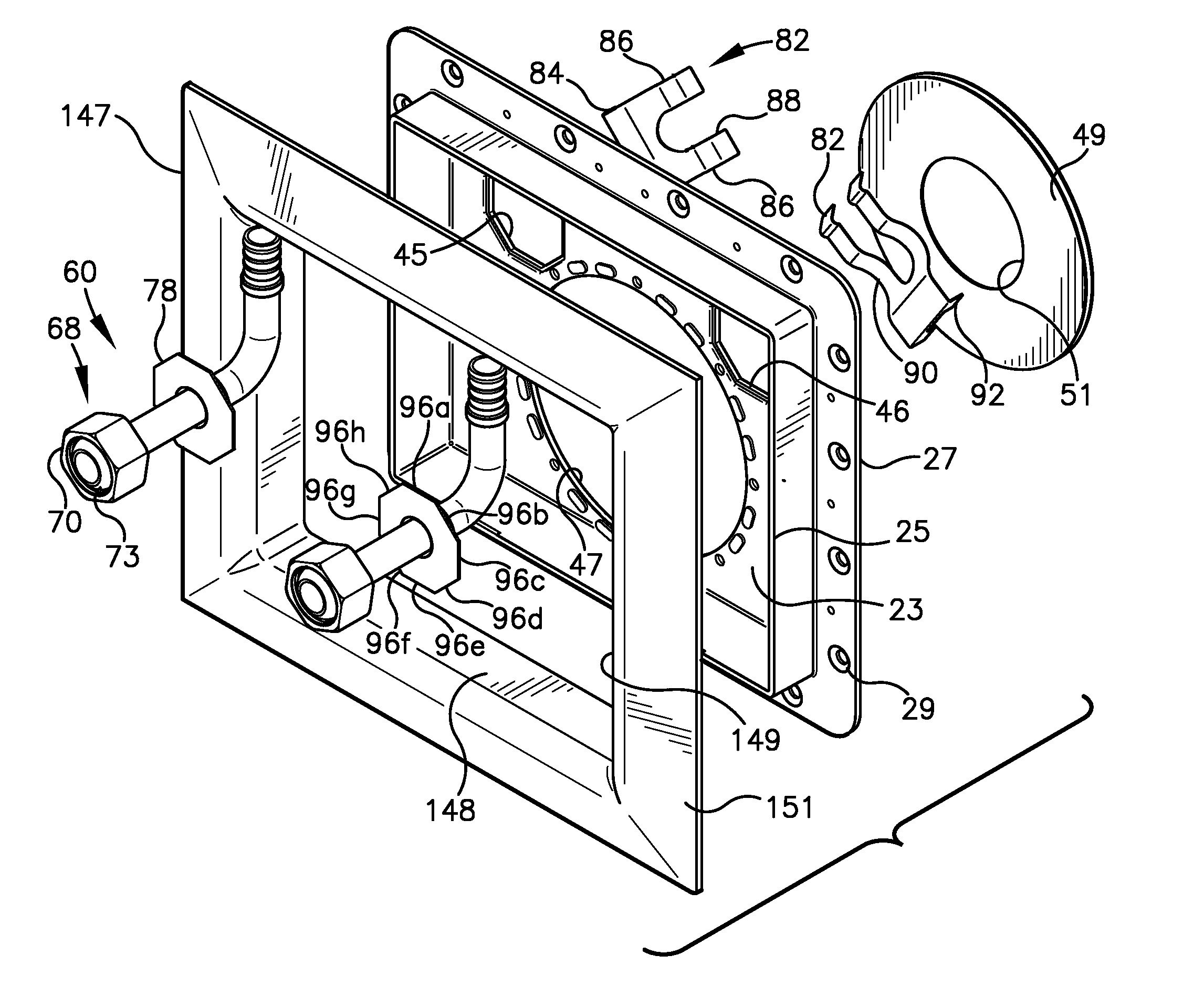
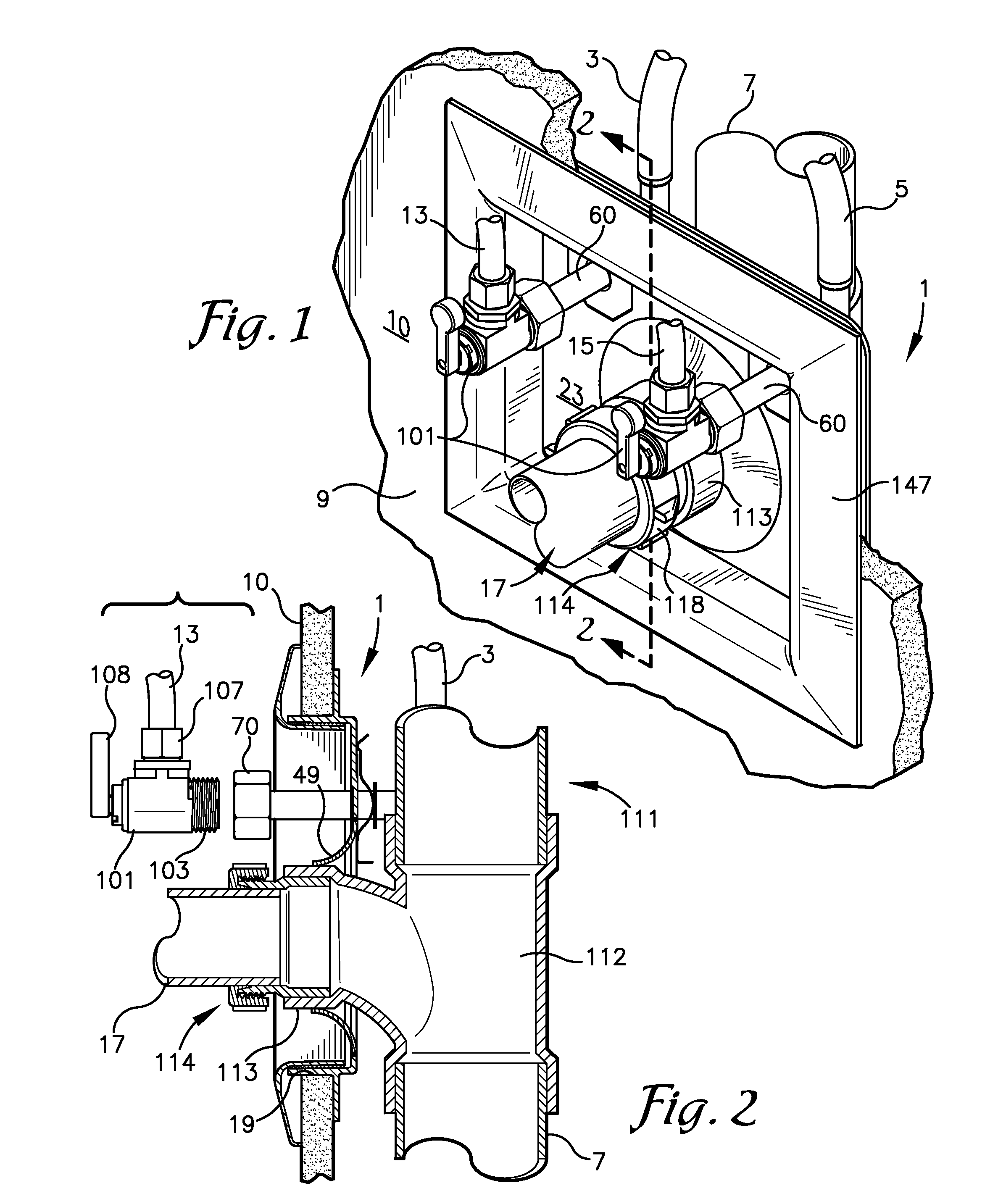
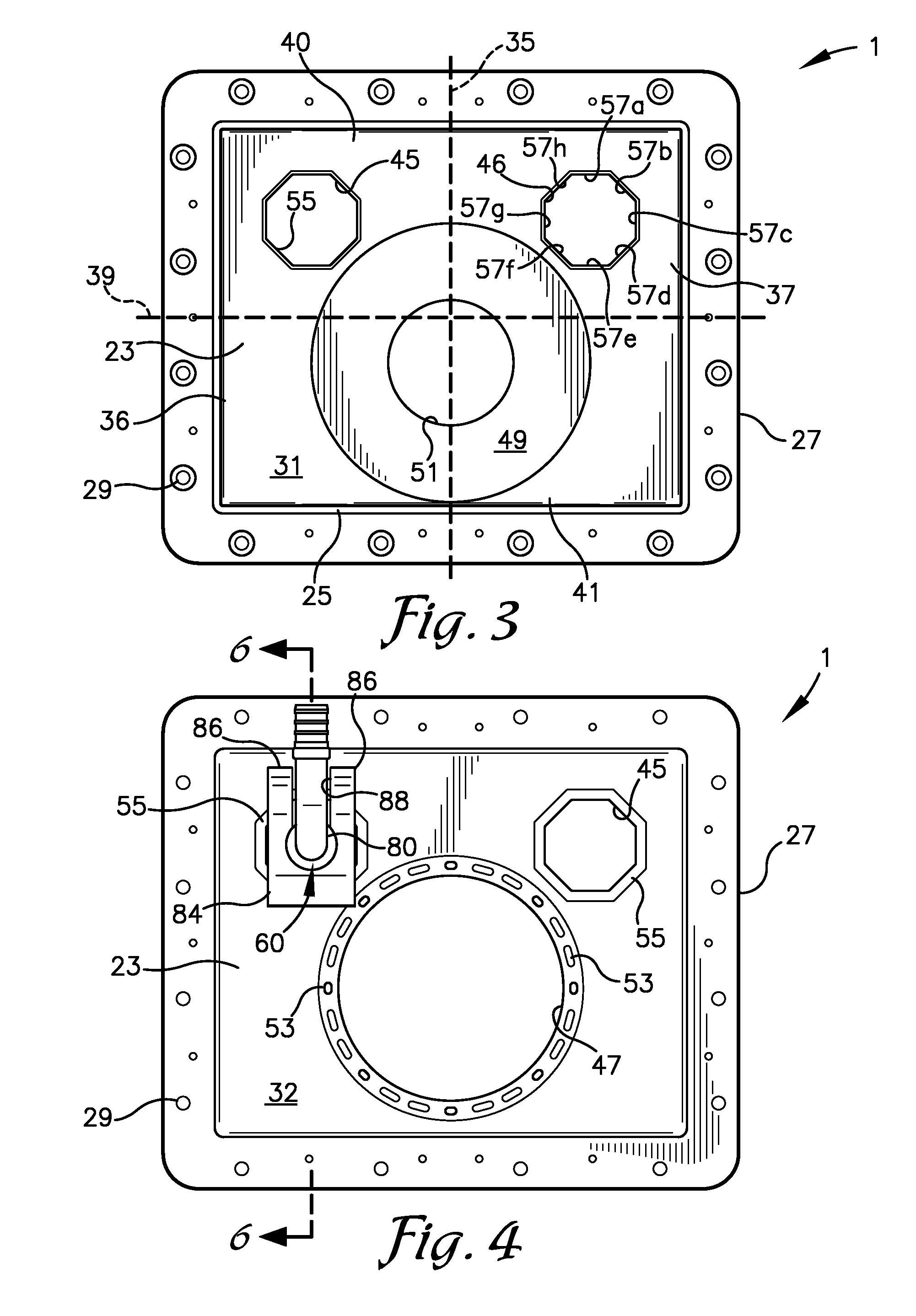
The assembly is a plumbing finish plate that can be used to cover an opening in a wall for water supply and drain lines. It includes a mounting panel with two openings for supply lines and one opening for the drain line. A flexible seal is connected to the drain line opening to seal around a drain pipe. A connector assembly is attached to the mounting panel through the supply line opening. The connector assembly includes an elbow with inlet and outlet connectors. It can be securely attached to the mounting panel using a clip, with the elbow positioned at least 90 degrees relative to the mounting panel. This assembly can be used with a mounting panel that has either one or both of the openings for supply lines and drain lines.

Problems solved by technology

Tying in supply lines and the drain line for sinks or lavatories in a stud wall can be a difficult and time consuming exercise, particularly where the connection of the supply and drain lines through the wall are exposed beneath the sink.
Finishing a wall around the drain line can prove difficult and time consuming, particularly if the drain line is stubbed out through the wall at an angle other than ninety degrees relative to the wall.
Although the orientation of the box can be changed to accommodate variations in the direction that the water supply lines and the drain line are plumbed to the box, the variations are limited.
There are numerous instances where due to the direction from which the supply lines and the drain line are plumbed, that use of the box taught in the Condon '254 patent is not usable.
In addition, in boxes such as are taught by Condon '254, it is very difficult to fit tools into the box to try to remove and replace the valve body if it develops a leak or otherwise fails.
Then once a new valve is obtained, it becomes difficult to install the valve by threading it onto a threaded receiver in the box while getting the supply line outlet of the valve to face forward without over or under tightening the valve body to the threaded receiver or without damaging the supply line connected thereto past the floor panel.

Method used


Image

  • Plumbing supply line and drain line mounting and finish panel
  • Plumbing supply line and drain line mounting and finish panel
  • Plumbing supply line and drain line mounting and finish panel

Examples


Embodiment Construction

[0030]As required, detailed embodiments of the present invention are disclosed herein; however, it is to be understood that the disclosed embodiments are merely exemplary of the invention, which may be embodied in various forms. Therefore, specific structural and functional details disclosed herein are not to be interpreted as limiting, but merely as a basis for the claims and as a representative basis for teaching one skilled in the art to variously employ the present invention in virtually any appropriately detailed structure. The drawings constitute a part of this specification and include exemplary embodiments of the present invention and illustrate various objects and features thereof.

[0031]Certain terminology will be used in the following description for convenience in reference only and will not be limiting. For example, the words “upwardly,”“downwardly,”“rightwardly,” and “leftwardly” will refer to directions in the drawings to which reference is made. The words “inwardly” a...


PUM


Abstract

A plumbing finish plate assembly, for connecting water supply lines and a drain line in a wall to fixture supply and drain lines, comprises a mounting panel having a drain line opening and two supply line openings formed therethrough. The drain line opening is larger than the supply line openings and a flexible, annular seal is secured around the drain line opening. A supply line connector assembly is securable to the mounting panel through each supply line opening. A securement means, in the form of a clip is used to selectively secure the supply line connector assembly to the mounting panel such that an outlet leg of the connector assembly is oriented in at least ninety degree increments relative to the mounting panel.

Description

BACKGROUND OF THE INVENTION[0001]1. Field of the Invention[0002]This invention relates to apparatus for attaching or connecting water supply lines and drain lines to a wall structure and which provides an acceptable finished appearance while sealing the opening around the drain line as well as the supply line.[0003]2. Description of the Related Art[0004]Tying in supply lines and the drain line for sinks or lavatories in a stud wall can be a difficult and time consuming exercise, particularly where the connection of the supply and drain lines through the wall are exposed beneath the sink. A wide variety of brackets, straps and the like are available for supporting and holding hot and cold water supply lines within a stud bay at the location where the supply lines will extend through holes formed in dry wall attached over the studs forming the stud wall. The branch of a drain line to which the sink drain is to be connected is typically self-supported off of a vertically extending drai...

Claims


Application Information

Patent Timeline
Patent Type & Authority Patents(United States)
IPC IPC(8): E03C1/02F16L5/10E03C1/12F16L5/14
CPCF16L5/14F16L5/10E03C1/021E03C1/12E03C2001/028Y10T137/698
Inventor ISMERT, BRIAN E.ISMERT, JOSEPH P.
Owner SIOUX CHIEF MFG
Features
  • R&D
  • Intellectual Property
  • Life Sciences
  • Materials
  • Tech Scout
  • Unparalleled Data Quality
  • Higher Quality Content
  • 60% Fewer Hallucinations
Learn More