Controlled electro-pneumatic power tools and interactive consumable

a technology of electro-pneumatic power tools and interactive consumables, which is applied in the direction of portable power-driven tools, transmissions, turning apparatuses, etc., can solve the problems of frequent unreachable optimum parameters, affecting the rotational speed at which the consumable is used has a direct influence on the performance and wear of the consumable,

Active Publication Date: 2015-06-23
FORGUES SYLVAIN +1
View PDF28 Cites 835 Cited by
  • Summary
  • Abstract
  • Description
  • Claims
  • Application Information

AI Technical Summary

Benefits of technology

[0020]According to the above features, from a broad aspect, the present invention provides a consumable accessory for use with a controlled electro-pneumatic power tool. The consumable accessory has a communication means associated therewith. The communication means, when transmitted to a microcontroller associated with the electro-pneumatic power tool, permits the microcontroller to access operational parameters of the accessory for operating the electro-pneumatic power tool with the consumable accessory secured thereto within the operational parameters and with continuous monitoring and automatic control of the electro-pneumatic power tool.

Problems solved by technology

Unfortunately, optimum parameters are seldom available to the operator person using the hand held power tool.
For example, the rotational speed at which the consumable is used has a direct impact on its performance and wear.
The problem is that the operator person is often unaware of the optimal speed for the consumable.
Furthermore, he often only has a single power tool to work with and has a tendency of running at the maximum speed for the power tool even if this maximum speed is much higher than the optimal speed for the consumable.
It is possible to calculate the optimal speed for a consumable but the calculation is mathematically complex and requires data and parameters not typically accessible to the operator person.
The use of consumables at inadequate speeds has led to numerous injuries to operator persons when the consumable breaks down or detaches from the spindle and hits the body of the operator person or someone nearby.
Furthermore, using consumables at inadequate speeds often leads to the rapid wear of the consumable which significantly increases the cost of the process.
Additionally, inadequate rotational speed can damage the part being treated by causing excessive heat or abrasion.
This may lead to the replacement of the part further increasing the cost of the process by several orders of magnitude.
When the wrong power tool is used and / or the wrong speed selected, the rotary cutters made of hard plastic can quickly disintegrate and damage the underlying base material like paints, primers, alodine, and metal.
In both cases, the cost of using the wrong rotational speed for the job can be very high.
When the rotational speed of the drill bit is too high, excessive heat is produced by the drilling which quickly burns the tip of the drill bit making it ineffective.
When the optimum speed is not used, abrasive wheels and disks can quickly bring the component thickness below its acceptable minimum limit.
Furthermore, the wrong speeds can generate heat on the surface thus modifying the heat treatment of the part.
In general, controlled power tools are not currently available for maintenance work on critical components.
Most electric power tools with drives do not use control methods with closed loop feedback to adjust the speed in real time.
This greatly reduces the responsiveness of the power tool when used under variable load by an operator person.
However, pneumatic power tools are known for more variability in the rotational speed mainly because of the fluctuations in the supply of compressed air.

Method used


Image

  • Controlled electro-pneumatic power tools and interactive consumable
  • Controlled electro-pneumatic power tools and interactive consumable
  • Controlled electro-pneumatic power tools and interactive consumable

Examples


Embodiment Construction

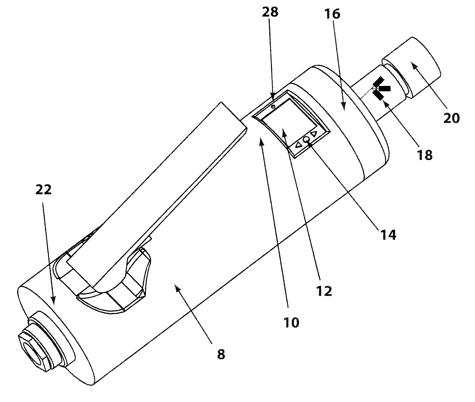
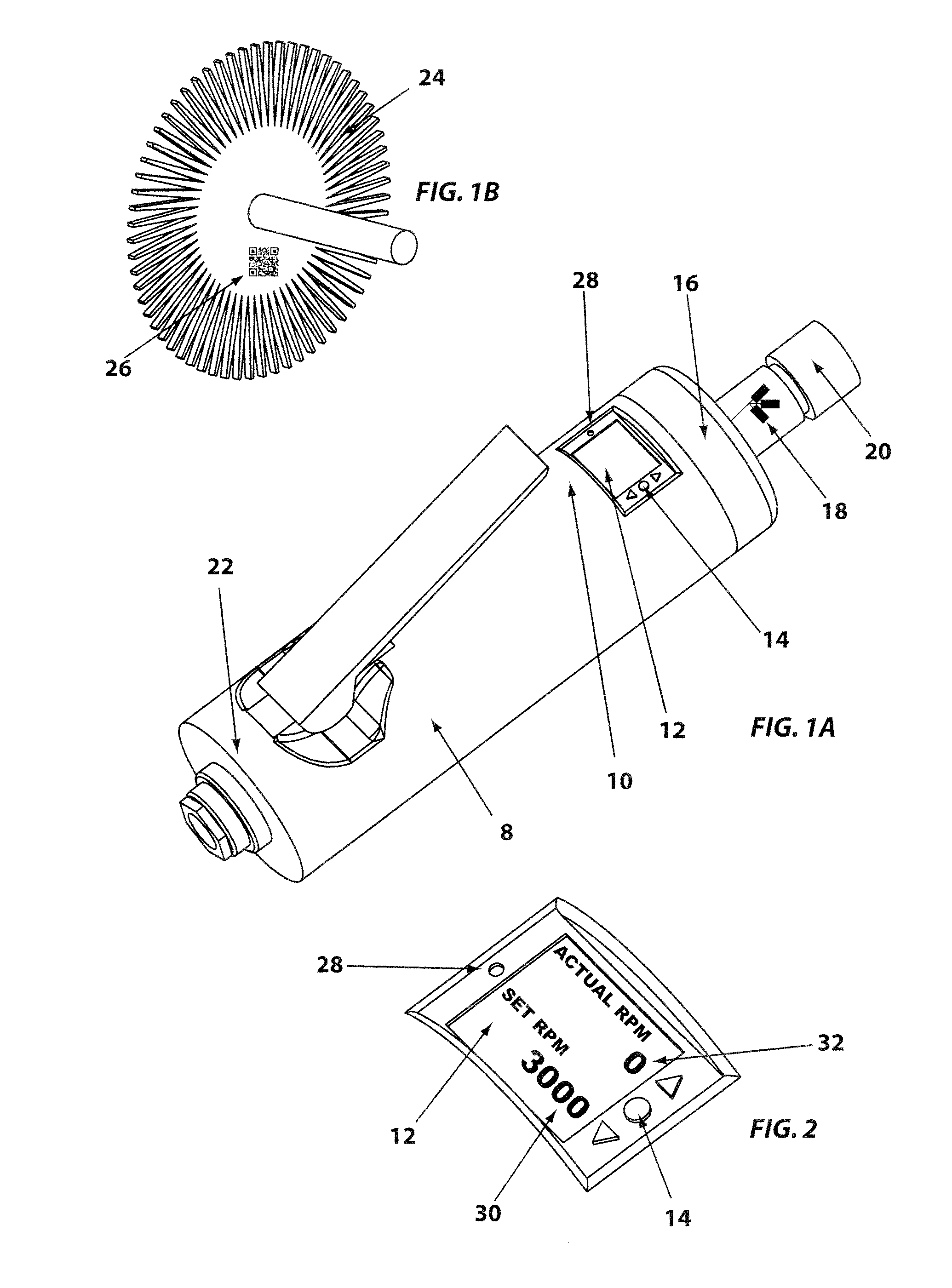
[0032]Referring to the drawings in greater detail and by reference characters thereto, there is illustrated in FIG. 1A a controlled electro-pneumatic power tool 8 with integrated microcontroller 10 and user interface 12 including an LCD screen, input buttons 14 and an internal buzzer. Other user interfaces such as lights and an audio output port connecting to an audio headphones or ear bud may also be used. The controlled electro-pneumatic power tool contains a rotational speed sensor 16 that feeds rotational speed information to the microcontroller in real time. The controlled electro-pneumatic power tool may also contain other types of sensors that could be used to feedback strands to the microcontroller to find the optimal rotational speed. Other sensors may include strain gauges 18 in the form of rosettes that can measure the applied force or pressure on the tool as well as the torque of the rotating shaft 20. A thermocouple could also be used as a sensor to measure the temperat...


PUM


Abstract

A controlled electro-pneumatic power tool includes an electro-mechanical adjustable valve, a pneumatic motor and a rotational speed sensor connected to a microcontroller for the selection, monitoring and adjustment adjustment of the rotational speed in real time. Using the communication port data for the consumable can be transmitted to the controlled electro-pneumatic power tool. The controlled electro-pneumatic power tool can read and utilize the transmitted data to select, adjust and maintain the optimum process parameters for the consumable without any input from the operator person. Furthermore, the communicated data can be used to warn the operator person that the tool used is inadequate for the selected consumable.

Description

CROSS-REFERENCE TO RELATED APPLICATION[0001]This application is a C-I-P of application Ser. No. 12 / 974,064, filed Dec. 21, 2010 now abandoned, which is a C-I-P of application Ser. No. 12 / 460,836, filed Jul. 24, 2009 now U.S. Pat. No. 7,954,348 and which claims priority based on U.S. Provisional Application Ser. No. 61 / 135,993 filed Jul. 25, 2008.TECHNICAL FIELD[0002]The present invention relates in general to the optimal use of pneumatic power tools, and more specifically, to controlled electro-pneumatic power tools with interactive consumables. Both the consumable and the controlled electro-pneumatic power tool incorporate a communication method to transfer important data pertaining to the optimal use of the consumable.[0003]By using this data to set optimal usage parameters, the controlled electro-pneumatic power tool will increase the safety of the operator person, improve the quality and reliability of his work and reduce the potential damages to parts being treated.BACKGROUND O...

Claims


Application Information

Patent Timeline
Patent Type & Authority Patents(United States)
IPC IPC(8): G06F19/00B23B31/00B24B23/02B24B49/00B24B49/14B24B55/00B24D5/02B24D13/10B25F5/00B25B17/00
CPCB24B23/026B23B31/005B24B49/006B24B49/14B24B55/00B24D5/02B24D13/10B25F5/001B23B2260/104
Inventor FORGUES, SYLVAINLABELLE, BRIGITTE
Owner FORGUES SYLVAIN
Why Eureka
Try Eureka