Electrical system lock out switch

a technology for electrical actuation systems and lockout switches, applied in the direction of protective switch operating/releasing mechanisms, switch distinguishing marks, protective switch distinguishing marks, etc., can solve the problems of difficult installation of lockout solutions, many lockout and tagout solutions perform well, and none of them are foolproo

Active Publication Date: 2015-06-23
HAMILTON SUNDSTRAND CORP
View PDF8 Cites 9 Cited by
  • Summary
  • Abstract
  • Description
  • Claims
  • Application Information

AI Technical Summary

Problems solved by technology

Thus, it is possible that after the equipment is isolated at the power source it may be inadvertently powered on by other personnel who do not know that the equipment was intentionally powered off.
While many lock-out and tag-out solutions perform well, none are fool proof.
Lock-out solutions are often difficult to install and require that the device being locked is pre-equipped with a lock receiving apparatus.
As aircrafts convert systems previously using hydraulic controls to new electrical solutions, issues arise in preventing unintended start-up of equipment.
Many of these systems on an aircraft have large moving surfaces that can create a safety hazard if they were to accidentally move while maintenance personnel are working on them or a neighboring engine.

Method used


Image

  • Electrical system lock out switch
  • Electrical system lock out switch
  • Electrical system lock out switch

Examples


Embodiment Construction

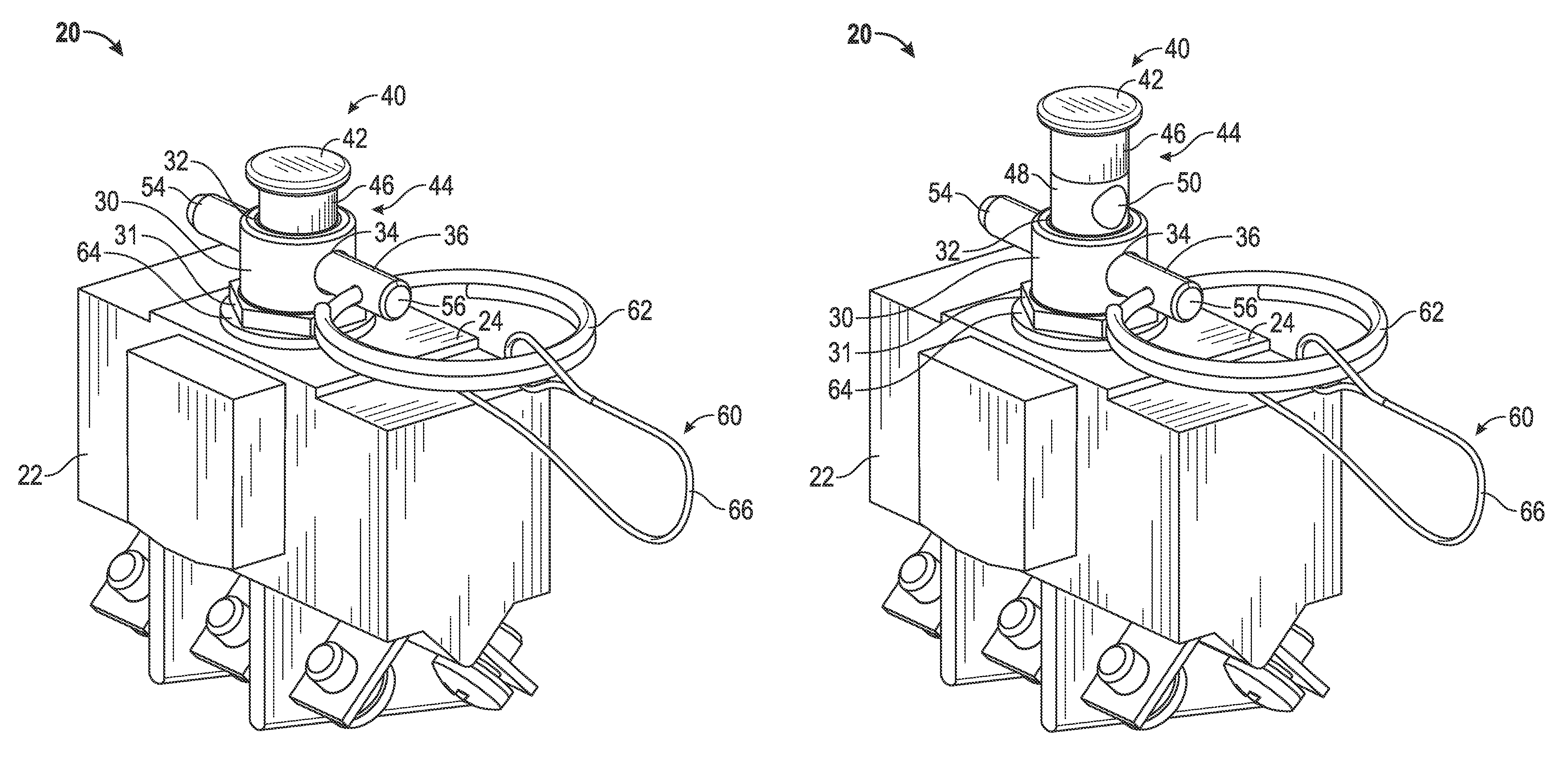
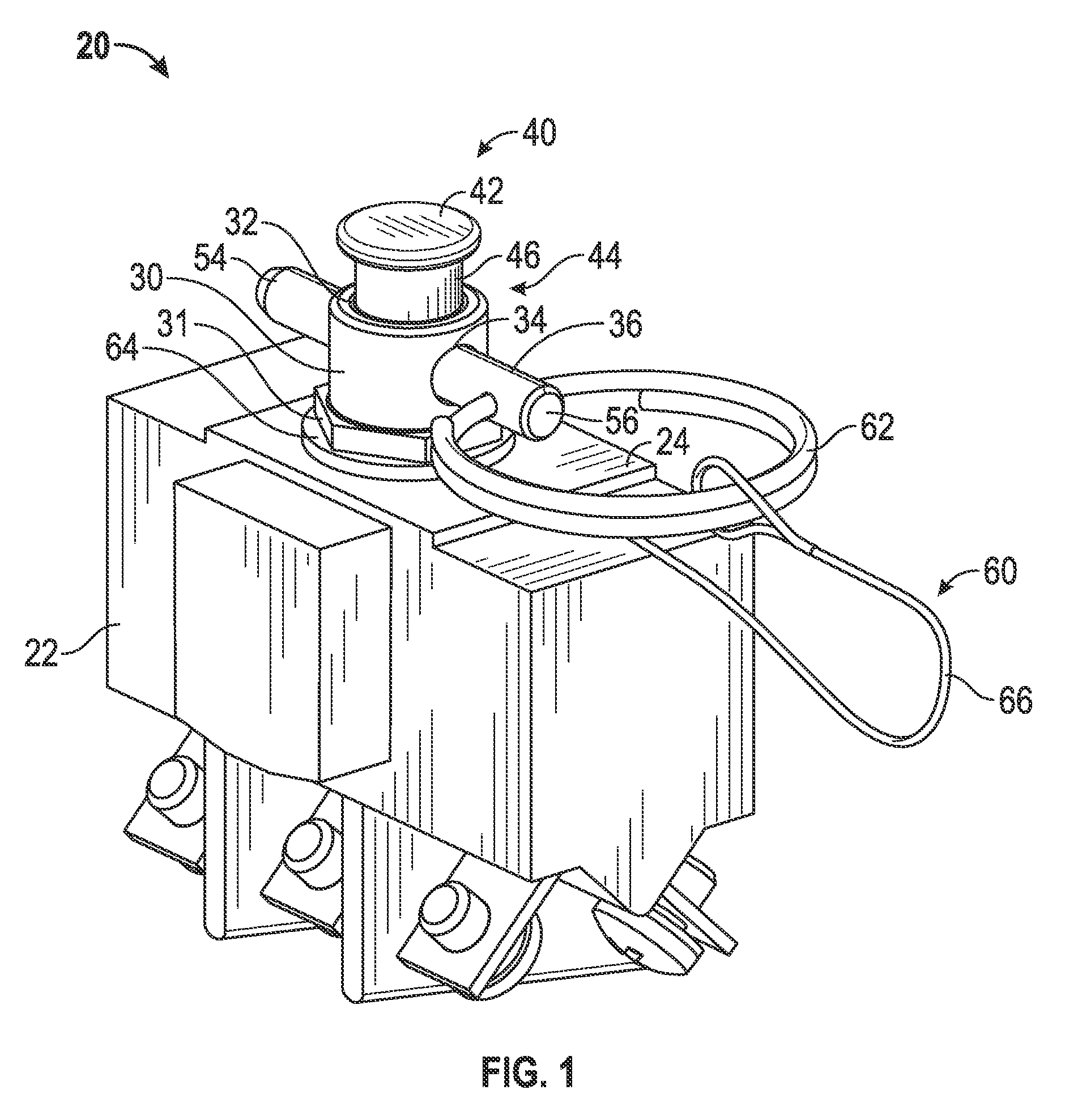
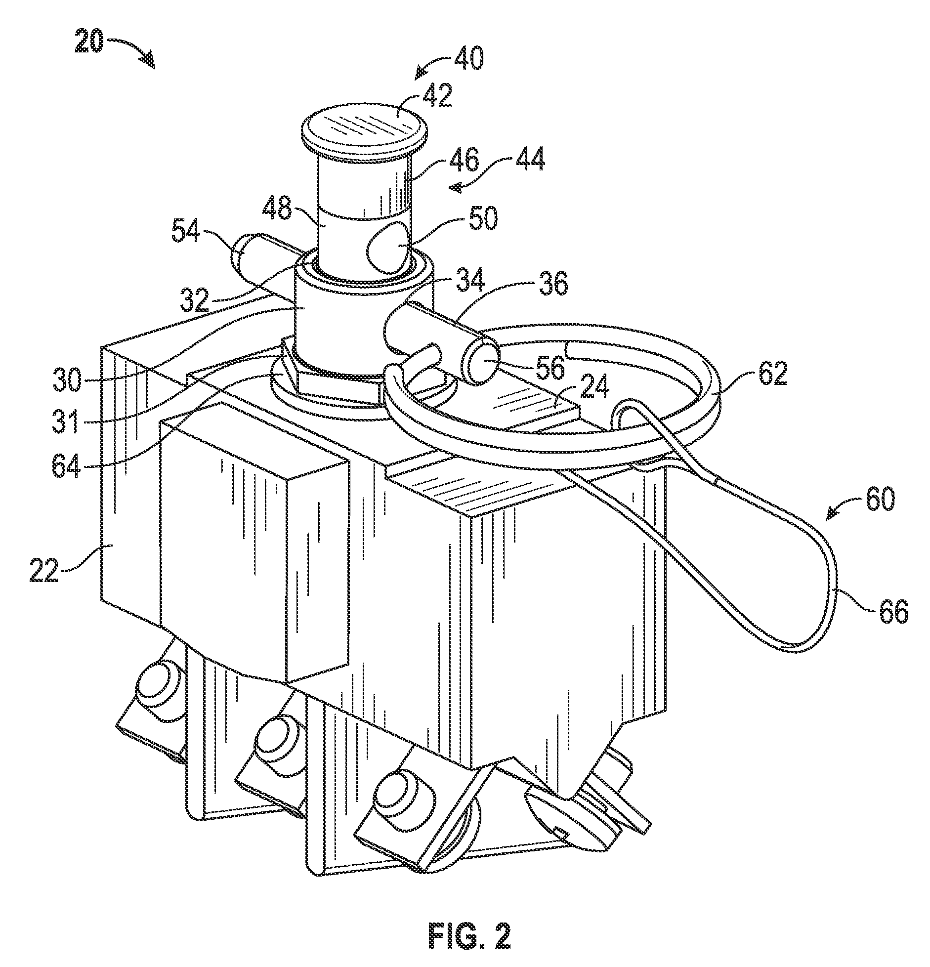
[0014]Referring now to the FIGS., an electrical switch 20, such as from an electrically actuated thrust reverser system or an electrically actuated variable area nozzle system of an aircraft is illustrated. In the illustrated embodiment, the electrical switch 20 is a three pole single throw switch (3PST) having an auxiliary switch for position status. Alternative electrical switches, such as a four pole single throw switch (4PST) that uses the fourth pole for position status for example, are within the scope of the invention. Configured to be mounted to a panel (not shown) in a conventional manner, the electrical switch 20 is arranged within a power feed line of the electrical actuation system and supplies power to a downstream component of the actuation system, such as a motor for example.

[0015]A stem guide 30 having a central bore 32 is aligned with and positioned next to an opening (not shown) in the upper surface 24 of the switch box 22. In one embodiment, the stem guide 30 is t...


PUM


Abstract

An electrical switch for use in an electrical actuation system is provided including a switch box having an upper surface with an opening. A stem guide is coupled to the switch box adjacent the opening. A lock out mechanism is received within a central bore of the stem guide and the opening. The lock out mechanism is configured to move between a first position and a second position to selectively break a flow of power through the electrical switch. A pin is configured to couple the lock out mechanism to the stem guide in one of the first position or the second position.

Description

BACKGROUND OF THE INVENTION[0001]Exemplary embodiments of this invention generally relate to electrical actuation systems and, more particularly, to a lock-out solution for an electrical actuation system of an aircraft.[0002]During installation, service and maintenance of powered equipment, service personnel, such as electricians for example, must assure that the equipment being worked on is isolated from its power source. Although the power source is usually electrical, other power sources such as mechanical, hydraulic, pneumatic, chemical, and thermal may be involved.[0003]When the power source and the equipment are arranged generally at the same location, isolation is not difficult. However, it is common that the power source, e.g. a breaker box, is located relatively far away from the equipment in need of service. Thus, it is possible that after the equipment is isolated at the power source it may be inadvertently powered on by other personnel who do not know that the equipment ...

Claims


Application Information

Patent Timeline
Patent Type & Authority Patents(United States)
IPC IPC(8): H01H9/28H01H13/14H01H9/16H01H71/58H01H71/06H01H71/04H01H73/16
CPCH01H9/286H01H73/16H01H9/16H01H13/14H01H71/04H01H71/06H01H71/58
Inventor WAVERING, JEFFREY T.
Owner HAMILTON SUNDSTRAND CORP
Why Eureka
Try Eureka