Rapid tuning frequency adjustable mobile HF communication antenna

a mobile hf communication and frequency adjustment technology, applied in the direction of elongated active element feed, resonant antenna, radiating element structure, etc., can solve the problem that hundreds or thousands of miles apart cannot utilize direct line-of-sight paths, the ion concentration in the ionosphere is unpredictable, and the two-way radio communication between locations is spaced at substantial distances, so as to increase the input impedance of the antenna, increase the effective electrical length of the antenna, and reduce the magnitude of the reactiv

Inactive Publication Date: 2015-06-23
ALASKA ENERGY SERVICES LLC
View PDF3 Cites 2 Cited by
  • Summary
  • Abstract
  • Description
  • Claims
  • Application Information

AI Technical Summary

Benefits of technology

[0011]An object of the present invention is to provide a rapid tuning frequency adjustable mobile communication antenna which enables the antenna to efficiently transmit and receive radio signals over a relative wide range of selectable frequencies, particularly in the high frequency (HF) band between 2 MHz and 30 MHz.

Problems solved by technology

Two-way radio communications between locations spaced apart at substantial distances, e.g., tens, hundreds or thousands of miles apart cannot utilize direct line-of-sight paths, because of the curvature of the earth's surface.
Moreover, in addition to diurnal variation in ion concentrations in the atmosphere, a variation in the sun's output of protons, which can be substantial, causes the ion concentration in the ionosphere to vary in unpredictable ways.

Method used


Image

  • Rapid tuning frequency adjustable mobile HF communication antenna
  • Rapid tuning frequency adjustable mobile HF communication antenna
  • Rapid tuning frequency adjustable mobile HF communication antenna

Examples


Embodiment Construction

[0054]FIGS. 1-23 illustrate the structure and function of a rapid tuning frequency adjustable mobile HF communication antenna according to the present invention.

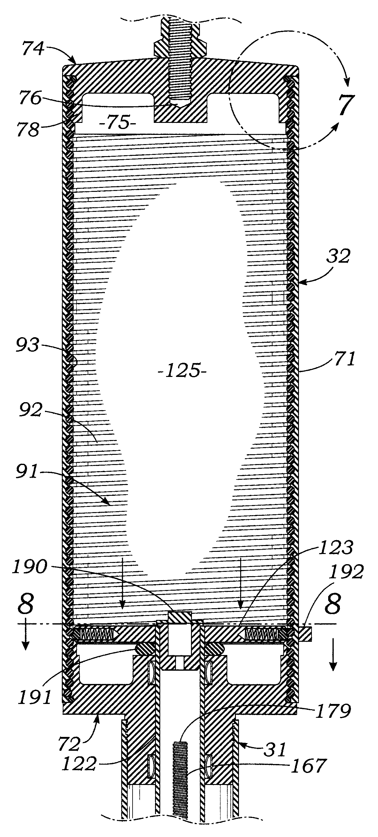
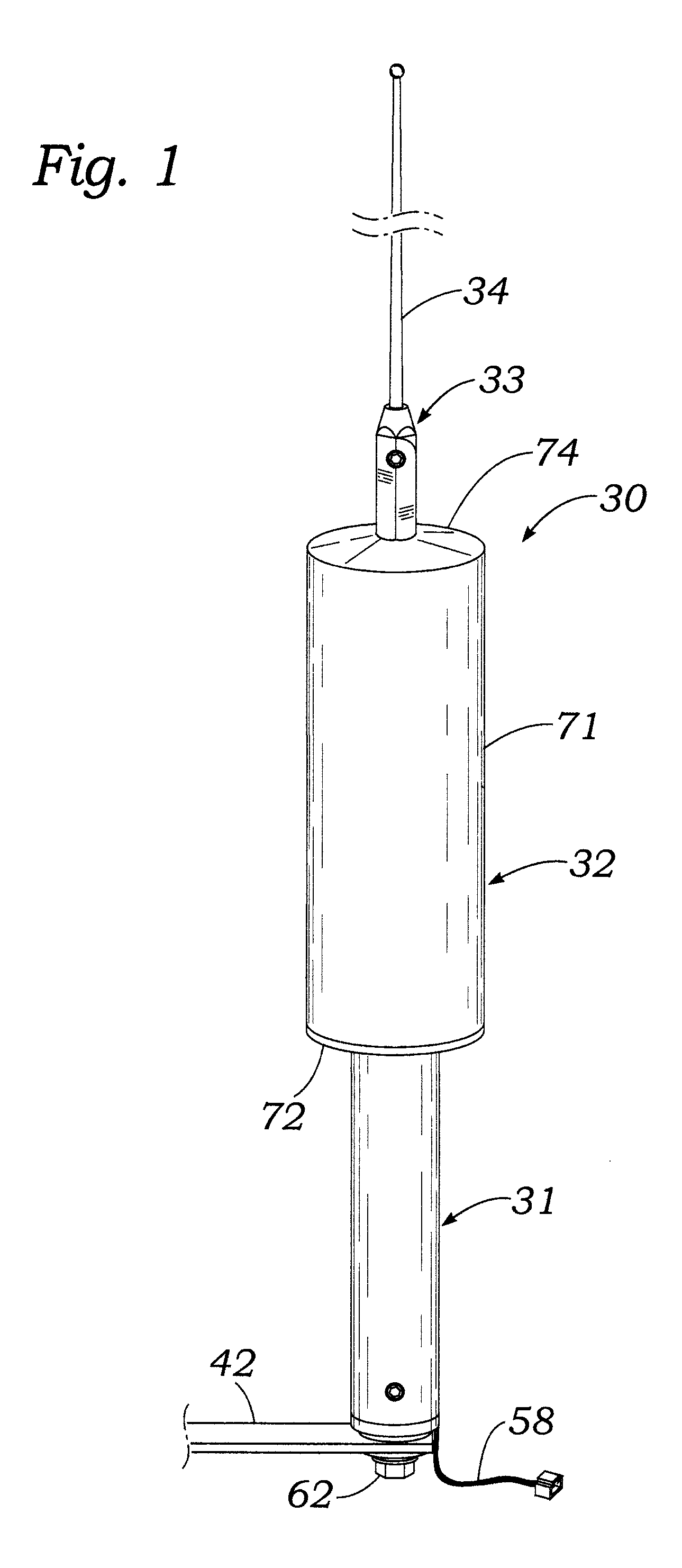
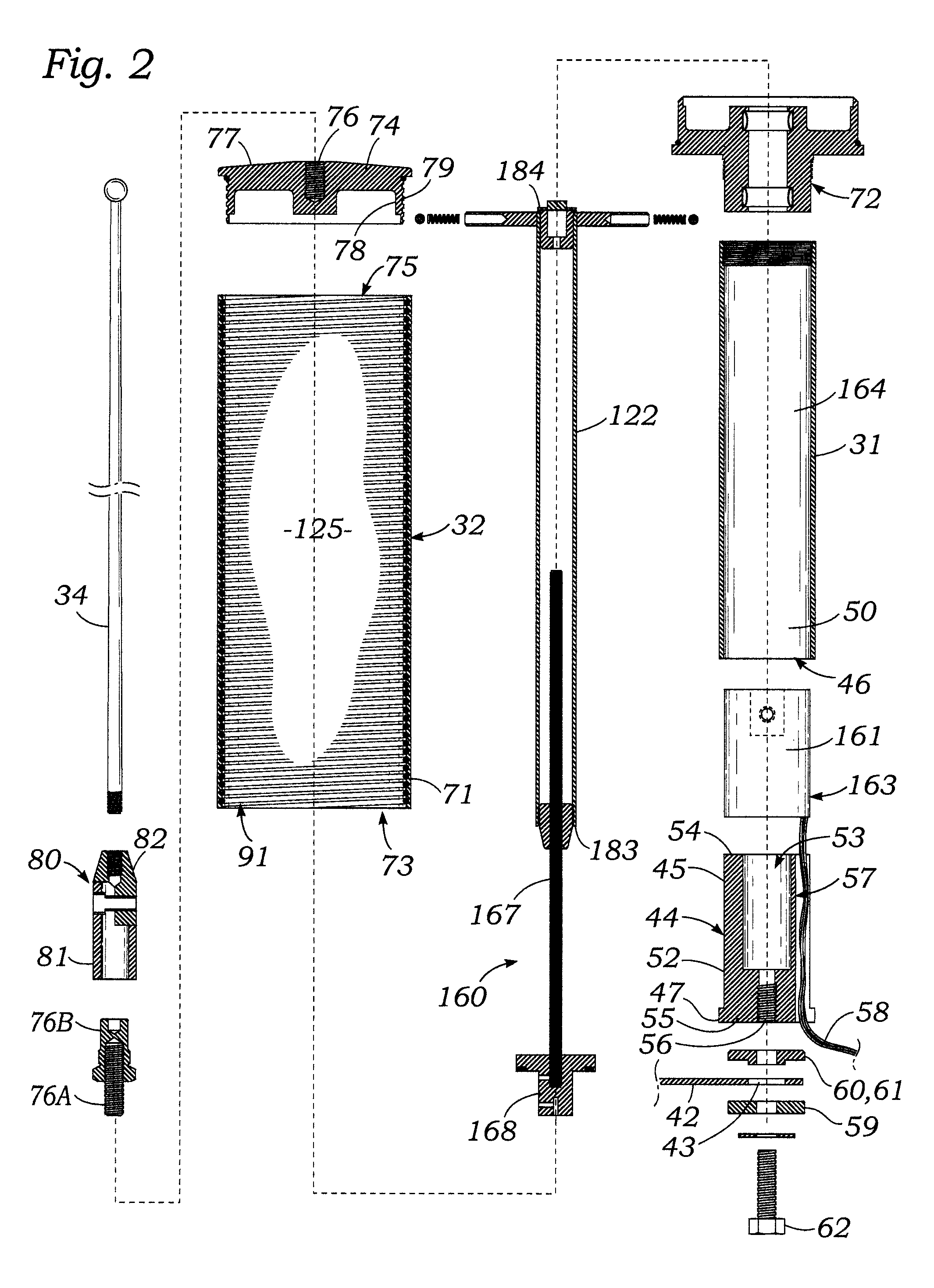
[0055]Referring first to FIG. 1, it may be seen that a rapid tuning frequency adjustable mobile HF communication antenna 30 according to the present invention has generally the shape of a straight, vertically elongated tubular body that consists of a coaxially aligned, vertical stack of circular cross-section cylindrically-shaped sections. The sections of antenna 30 include a bottom cylindrically-shaped tubular mast section 31 which has a diameter of about 2.5 inches and a length of about 2¼ feet. The mast section 31 has attached coaxially to its upper end an axially aligned coil tube section 32, which has a diameter of about 5½ inches, and a length of about 13 inches.

[0056]Antenna 30 includes a whip section 33 which has an elongated flexible whip antenna rod 34 which has a diameter of about ⅛ inch that extends perpendicular...


PUM


Abstract

A mobile high-frequency antenna rapidly adjustable to minimize VSWR and maximize transmitting and receiving efficiency includes a conductive whip mounted on a coil housing containing a solenoidal loading coil electrically connected at an upper end to the whip and at a lower end to a conductive mast which supports the coil housing. A coil contactor disk at the upper end of a conductive metal shaft raised or lowered by a stepper motor-driven lead screw has protruding spring loaded balls which rollingly contact inner surfaces of coil turns to thus insert less or more inductance between the shaft and whip to tune the antenna. A pair of RF de-couplers in a coil housing base plug which electrically contacts the mast and the lower end of the coil slidably support and electrically contact the shaft, thus shorting out lower parts of the coil to suppress harmonic currents from being induced therein.

Description

BACKGROUND OF THE INVENTION[0001]A. Field of the Invention[0002]The present invention relates to antennas used to transmit and receive high frequency (HF) radio signals in the approximate range of 2 MHZ to 30 MHZ. More particularly, the invention relates to an HF monopole antenna which is attachable to a motor vehicle and which is rapidly tunable to maximize efficiency of transmitting and receiving radio signals at different selected frequencies contained in a relatively wide band.[0003]B. Description of Background Art[0004]Two-way radio communications between locations spaced apart at substantial distances, e.g., tens, hundreds or thousands of miles apart cannot utilize direct line-of-sight paths, because of the curvature of the earth's surface. Therefore, such radio communications use radio frequency signals which operate in a high frequency range, e.g., 2 MHZ to 30 MHZ, because radio signals in the HF range are reflected from the earth's ionosphere. Thus, HF radio signals can be ...

Claims


Application Information

Patent Timeline
Patent Type & Authority Patents(United States)
IPC IPC(8): H01Q9/00H01Q21/30H01Q1/36H01Q9/30H01Q1/32
CPCH01Q9/30H01Q1/36H01Q21/30H01Q1/3258
Inventor GYENES, CHARLES M.
Owner ALASKA ENERGY SERVICES LLC
Why Eureka
Try Eureka