Vehicle radar antenna system for preventing collision

A radar antenna, vehicle collision technology, applied to antennas, radio wave measurement systems, antennas and other directions suitable for movable objects, and can solve the problems of difficulty in obtaining high isolation values, small dynamic range at the receiving end, and inability to detect long-range signals. , to achieve the effect of suppressing the reception of unnecessary signals, low price, and high antenna gain

Inactive Publication Date: 2019-03-15
TELTRON
View PDF2 Cites 0 Cited by
  • Summary
  • Abstract
  • Description
  • Claims
  • Application Information

AI Technical Summary

Problems solved by technology

On the other hand, there is a method that uses one antenna and attaches a circulator to the rear end of the antenna to isolate the use of the transmitting end and the receiving end, but in this case it is difficult to obtain a high isolation value (isolation)
If the isolation value is low, the dynamic range (Dynamic Range) of the receiving end will be reduced, so there will be a disadvantage of being unable to detect remote signals
[0003] In addition, in the current radar system for monitoring the rear and both sides, separate radars are installed in the center of the rear and at the corners of the left and right sides to monitor, which is an important factor that increases the price by 3 times compared to using one radar. cause, and has the disadvantage of increasing system complexity

Method used

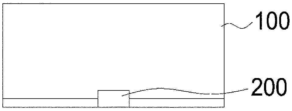
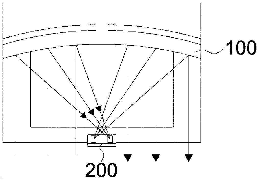
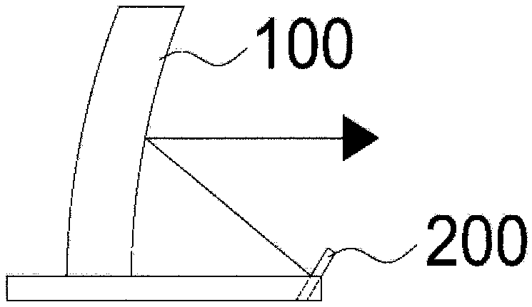

Image

  • Vehicle radar antenna system for preventing collision
  • Vehicle radar antenna system for preventing collision
  • Vehicle radar antenna system for preventing collision

Examples


Embodiment Construction

[0037] Hereinafter, preferred embodiments of the present invention will be described in detail with reference to the drawings, however, the present invention can be embodied in other forms and is not limited to the embodiments described here. On the contrary, the various embodiments introduced here are provided in order to make the disclosed content thorough and complete, and to fully convey the idea of ​​the present invention to those skilled in the art.

[0038] Therefore, the present invention can implement various changes and have various embodiments, and it should be understood that all changes, equivalents, and substitutions falling within the spirit and technical scope of the present invention are included.

[0039] On the other hand, in describing the present invention, when it is judged that the specific description of related known technologies may obscure the gist of the present invention, the detailed description will be omitted.

[0040] Terms such as "first" and ...


PUM


Abstract

The present invention relates to a vehicle radar antenna system for preventing vehicle collision which is installed in a vehicle, detects surrounding vehicles, and can prevent collision between the vehicles. The vehicle radar antenna system for preventing vehicle collision comprises: a parabolic reflection surface; and a feeding part located at a central focal part of the reflection surface, and transmitting and receiving radio waves. The feeding part includes: a patch feeding antenna for transmission transmitting the radio waves to the parabolic reflection surface; and a patch feeding antennafor reception receiving the radio waves from the parabolic reflection surface.

Description

technical field [0001] The present invention relates to a vehicle radar antenna system (radar antenna system) for preventing vehicle collisions, and more particularly, to a parabola transmitting / receiving antenna system that can be used in a vehicle collision prevention radar system, wherein , the vehicle collision prevention radar system is installed in the vehicle and can detect front, rear and side vehicles. Background technique [0002] Since the radar used to prevent car collisions uses frequencies of 24GHz, 77GHz, and 79GHz, the size of a single antenna is very small. Therefore, most antennas have a microstrip or coplanar planar antenna structure. This type of antenna combines several individual antenna elements in order to obtain a given gain and antenna pattern (Pattern) and is made into an array (array) form. However, this antenna has a characteristic of reduced effective gain due to large losses due to high radar frequencies. In addition, in the case of using th...

Claims


Application Information

Patent Timeline
Patent Type & Authority Applications(China)
IPC IPC(8): H01Q1/32H01Q15/16
CPCH01Q1/3291H01Q15/16G01S13/931H01Q1/32H01Q9/0407H01Q9/045
Inventor 李载珍
Owner TELTRON
Why Eureka
Try Eureka