Radio frequency antenna assembly

a technology of radio frequency antennas and antenna assemblies, which is applied in the direction of resonant antennas, elongated active element feeds, and different interaction antenna combinations, etc., can solve the problems of limiting the scope of use of devices and compromising the functionality of certain devices, and achieves low cost, efficient transmission and reception of rf signals, and low profile

Active Publication Date: 2022-06-09
RF VENUE
View PDF3 Cites 0 Cited by
  • Summary
  • Abstract
  • Description
  • Claims
  • Application Information

AI Technical Summary

Benefits of technology

The present invention provides an RF antenna that can efficiently transmit and receive RF signals through a panel of a shielded enclosure. It is reliable, low-profile, and has a limited number of parts, making it easy to manufacture and use. The technical effects of the invention include improved performance and reliability, as well as a compact design and economical manufacturing process.

Problems solved by technology

The growing number of wireless electronic devices within a relatively confined area can introduce electromagnetic interference, which can compromise the functionality of certain devices.
Electronic devices housed within an EFI / RFI-shielded enclosure typically rely upon a wired connection for data transmission, since wireless signals are largely incapable of transmission therethrough.
However, since most electronic devices are equipped with a limited number of ports, reliance upon a hardwired connection often limits the scope of use for the device.
Furthermore, it should be noted that certain electronic devices are only designed for wireless communication and therefore are generally precluded from being housed within such an enclosure.

Method used


Image

  • Radio frequency antenna assembly
  • Radio frequency antenna assembly
  • Radio frequency antenna assembly

Examples


Embodiment Construction

Radio Frequency (RF) Antenna System 11

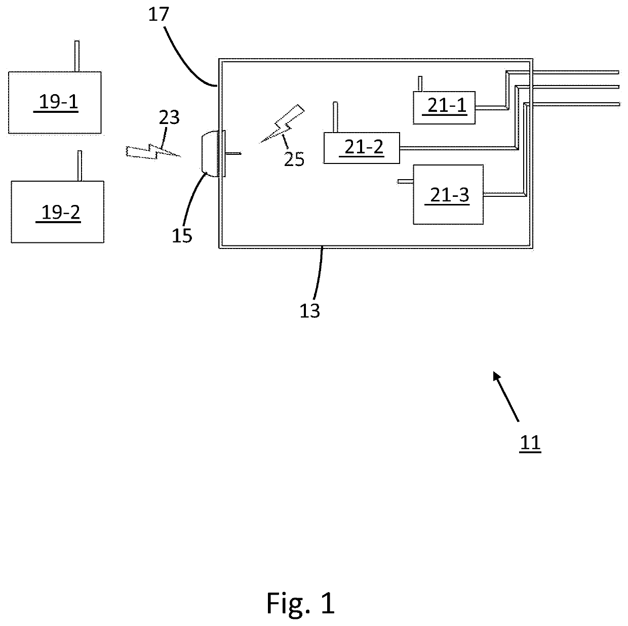
[0028]Referring now to FIG. 1, there is shown a radio frequency (RF) antenna system constructed according to the teachings of the present invention, the RF antenna system being defined generally by reference numeral 11. As will be explained in detail below, RF antenna system 11 is uniquely designed to assist in the transmission and receipt of RF signals within an RF attenuated environment.

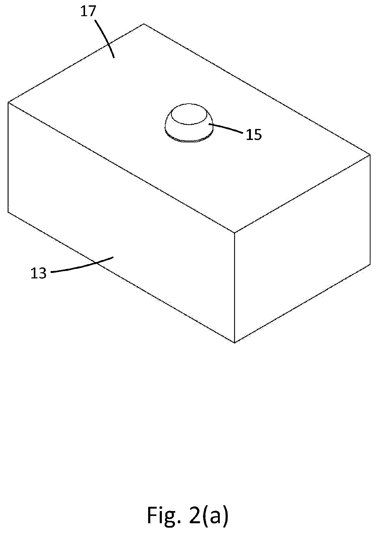
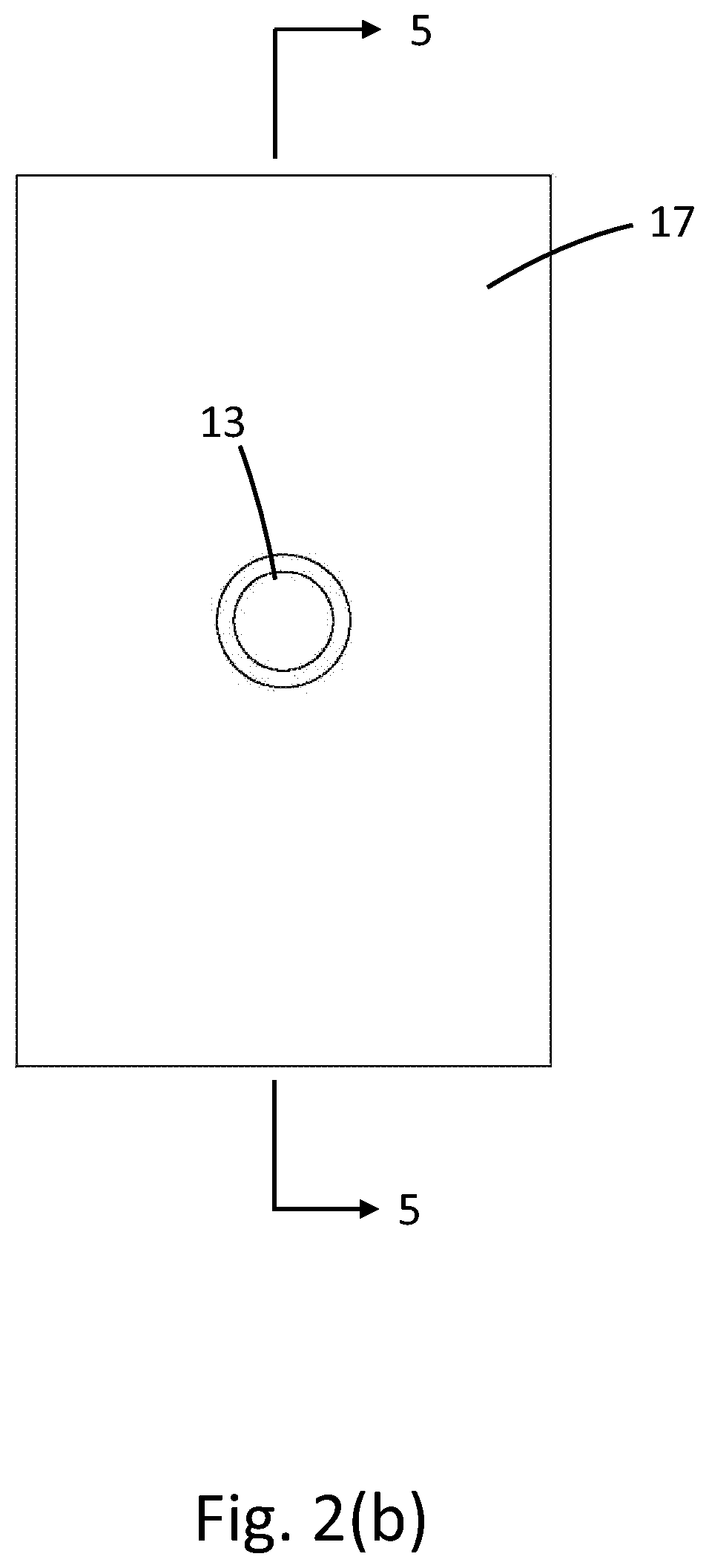
[0029]As can be seen, RF antenna 11 comprises (i) an RF-shielded enclosure, or cabinet, 13, (ii) a radio frequency (RF) antenna assembly 15 mounted on a panel 17 of enclosure 13, (iii) a first set of electronic devices with RF communication capabilities 19-1 and 19-2 located outside of enclosure 13, and (iv) a second set of electronic devices with RF communication capabilities 21-1 thru 21-3 located within enclosure 13. In use, antenna assembly 15 facilitates the transmission of RF signals between exterior devices 19 and interior devices 21. As will be describe...


PUM


Abstract

A radio frequency (RF) antenna assembly is mounted on a shielded panel to facilitate the transmission of RF signals therethrough. The RF antenna assembly includes an RF antenna formed from wire which is bent to define first and second antenna elements. The RF antenna is inserted through the panel with the first and second antenna elements disposed on opposite sides thereof. A dome-shaped cap constructed of a compressible elastomeric material is mounted over the first antenna element and lies flush against the outer surface of the panel. A disc-shaped dielectric base receives the distal end of the second antenna element and lies flush against the inner surface of the panel. The RF antenna exerts a spring-like force that resiliently draws the cap and base together. In use, each antenna element transmits RF signals within a designated frequency range to wireless electronic devices located on the same side of the panel.

Description

CROSS-REFERENCE TO RELATED APPLICATIONS[0001]The present application claims the benefit under 35 U.S.C. 119(e) to U.S. Provisional Patent Application No. 63 / 122,132, which was filed on Dec. 7, 2020, in the names of Robert J. Crowley et al., the disclosure of which is incorporated herein by reference.FIELD OF THE INVENTION[0002]The present invention relates generally to radio frequency (RF) antennas and, more particularly, to RF antennas designed to transmit and receive RF signals within RF attenuated environments.BACKGROUND OF THE INVENTION[0003]In the modern world, electronic devices are utilized to perform a wide array of tasks across an increasing number of settings. For instance, in a smart home, various electronic devices are designed to automatically monitor and / or control certain home attributes, such as lighting, security, temperature, and entertainment. Internet of Things (IoT) devices, such as smart home appliances, remotes, printers, and the like, have become prevalent in...

Claims


Application Information

Patent Timeline
Patent Type & Authority Applications(United States)
IPC IPC(8): H01Q1/52H01Q1/12H01Q1/38H01Q1/44
CPCH01Q1/526H01Q1/44H01Q1/38H01Q1/1214H01Q7/00H01Q9/42H01Q1/36H01Q1/42H01Q21/29H01Q25/005H01Q1/244
Inventor CROWLEY, ROBERT J.MORRISON, CALEB W.FENDROCK, CHARLES
Owner RF VENUE
Why Eureka
Try Eureka