Image pickup apparatus

a technology of image pickup and apparatus, which is applied in the direction of optical elements, television systems, instruments, etc., can solve the problems of performance degradation, difficult downsizing, and the ability to adjust the light amount only step by step, and achieve the effect of suppressing the color of blurred images

Inactive Publication Date: 2015-06-23
CANON KK
View PDF12 Cites 2 Cited by
  • Summary
  • Abstract
  • Description
  • Claims
  • Application Information

AI Technical Summary

Benefits of technology

[0013]According to the present invention, it is possible to provide the image pickup apparatus including the color separation optical system in which coloring of a blurred image is suppressed.

Problems solved by technology

In addition, when the stop is stopped down, performance degradation may occur due to diffraction phenomena and may cause a problem.
However, when using the filter disc, a space for holding multiple elements and a drive mechanism for switching the filter disc are necessary, and hence downsizing has been difficult.
In addition, there has been a problem that a filter holding frame appears as a shadow on a screen when switching the ND filter and a problem that the light amount can be adjusted only step by step.
Then, as a result, there is a problem that angle shading occurs in which unevenness is generated in luminance or color in the screen.
In particular, because it cannot be expected that how the image is blurred in the screen, the coloring of the blurred image cannot be electrically corrected, which becomes a large problem in a practical manner.

Method used


Image

  • Image pickup apparatus
  • Image pickup apparatus
  • Image pickup apparatus

Examples


first embodiment

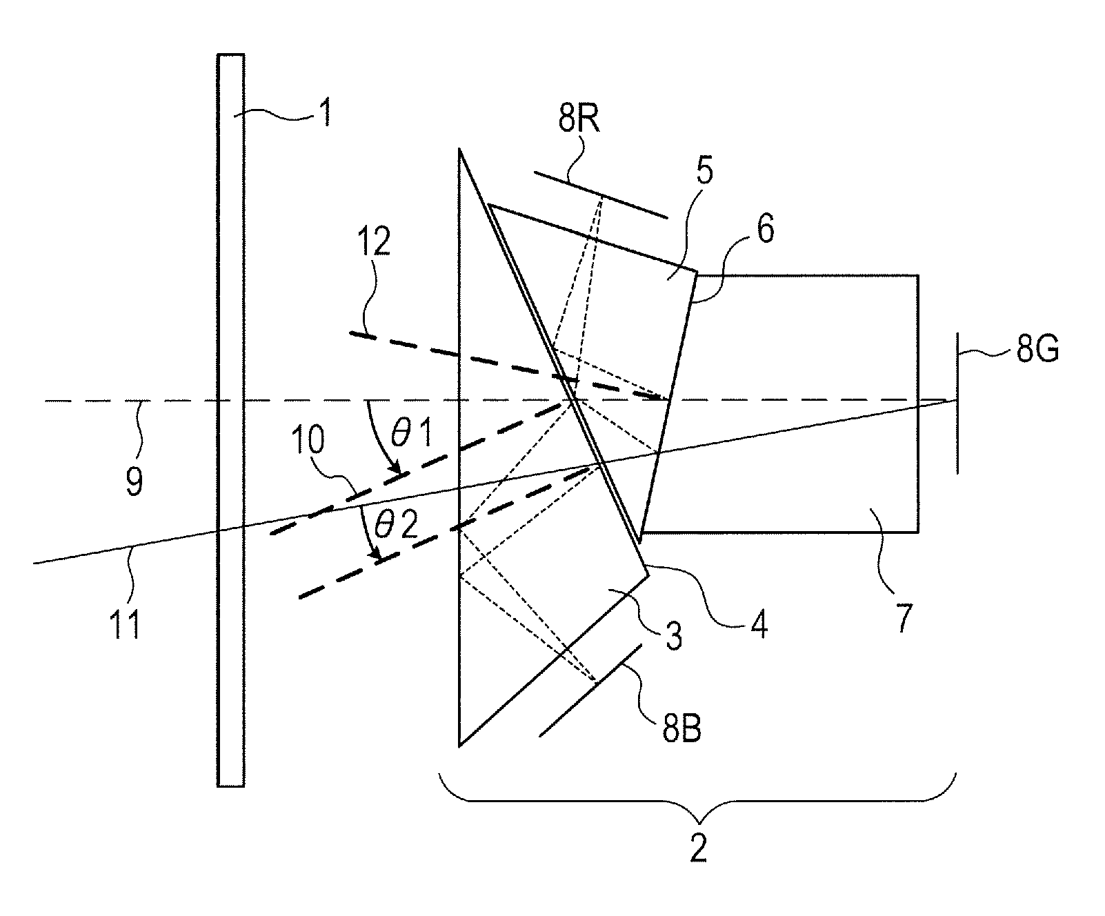
[0026]FIG. 1 illustrates a schematic diagram of main parts of a filter unit and a camera unit according to a first embodiment of the present invention.

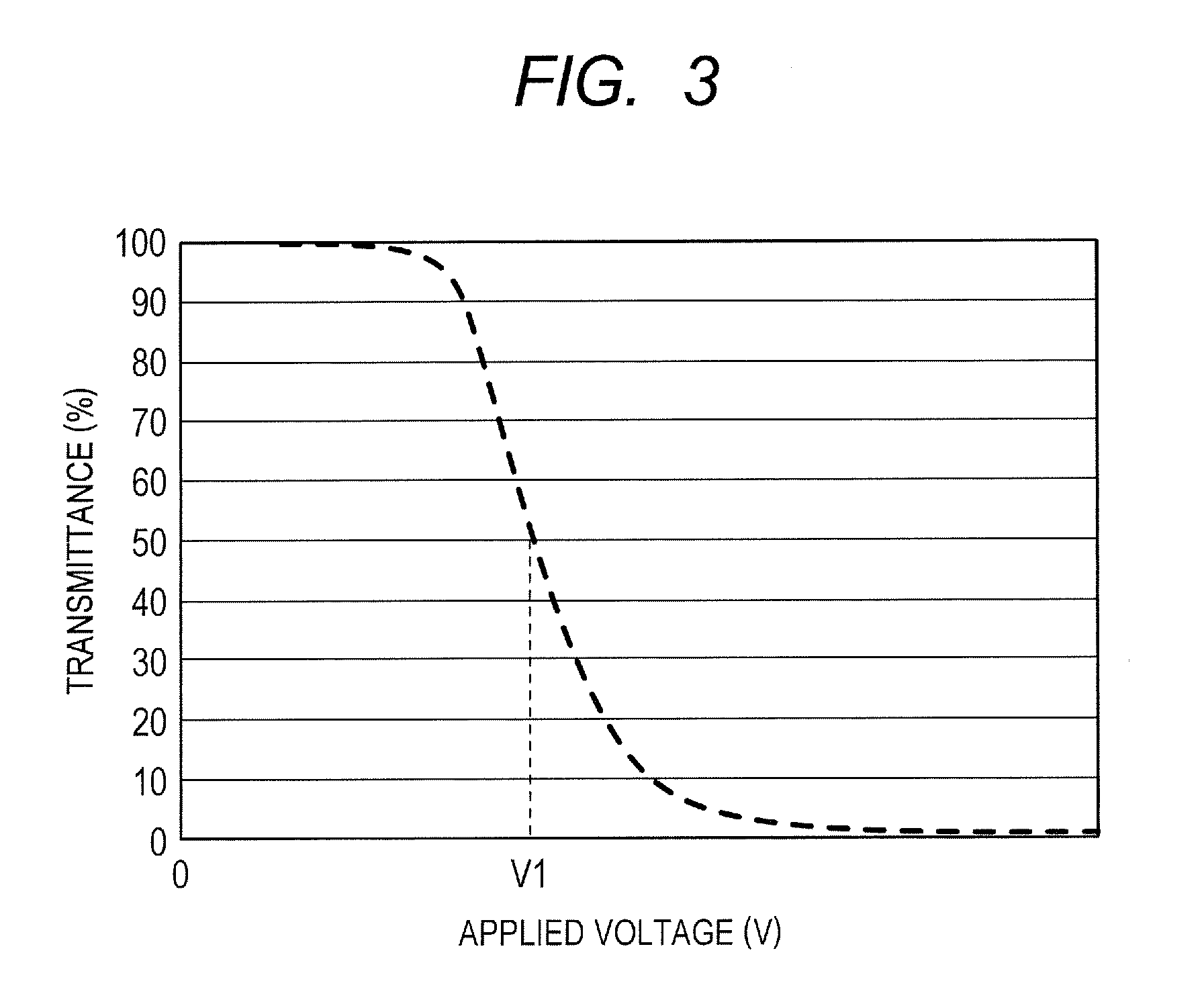
[0027]An image pickup apparatus of the present invention includes, in order from an object side, a filter unit for adjusting a light amount of subject light entering through a lens apparatus (image pickup optical system), and a camera unit for forming an image signal by photoelectric conversion of the subject light after passing through the filter unit by a photoelectric transducer. A transmittance variable element 1 as the filter unit is formed of a liquid crystal element (transmittance variable ND filter) and can continuously change the transmittance for the incident light by an applied voltage. The camera unit includes a color separation optical system 2 and image pickup elements 8B, 8R, and 8G. The color separation optical system (light guide optical system) 2 in this embodiment includes, in order from the object side, a blue sepa...

second embodiment

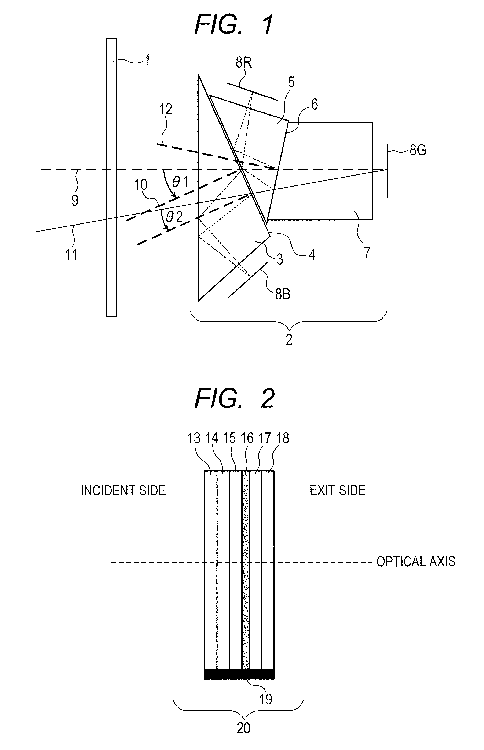
[0047]FIG. 9 illustrates a schematic diagram of a main part of an image pickup apparatus according to a second embodiment of the present invention.

[0048]In the image pickup apparatus of this embodiment, a structure of a color separation optical system 23 is different from that of the color separation optical system (light guide optical system) 2 in the first embodiment. The color separation optical system 23 of this embodiment includes, in order from the object side, a red separation prism 24 (first prism) with a red reflection dichroic film (first dichroic film) evaporated on the reflection surface, a blue separation prism 26 (second prism) with a blue reflection dichroic film 27 (second dichroic film) evaporated on the reflection surface, and a green separation prism 28 (third prism) for guiding the green color light to the image pickup element. In this embodiment, the incident light from a lens apparatus (not shown) passes through a transmittance variable element 22 having the sa...


PUM


Abstract

An image pickup apparatus, including: a filter including transmittance variable element and adjusting amount of incident light from lens; a photoelectric transducer; and guide optical system guiding the incident light from the filter to the photoelectric transducer. The guide optical system includes color separation optical system including, in order from object side, first prism having first dichroic film, second prism having second dichroic film, and third prism, to separate the incident light into red, green, and blue. The first or second dichroic film is blue reflection dichroic film. Rotational position of the transmittance variable element about optical axis is such a position that ratio of transmittance for blue to transmittance for green of marginal ray entering the blue reflection dichroic film at incident angle smaller than principal ray of axial ray to the blue reflection dichroic film is smaller than such ratio of the principal ray of axial ray.

Description

BACKGROUND OF THE INVENTION[0001]1. Field of the Invention[0002]The present invention relates to an image pickup apparatus, and more particularly, to an image pickup apparatus including a color separation optical system.[0003]2. Description of the Related Art[0004]Hitherto, when subject luminance is too high in an image pickup system, a predetermined amount or more of light may enter an image pickup element even though a stop is stopped down to a minimum diameter. In addition, when the stop is stopped down, performance degradation may occur due to diffraction phenomena and may cause a problem. Therefore, a neutral density (ND) filter is disposed between an image pickup lens and an image pickup element so as to limit an amount of light entering the image pickup element. As the ND filter, there is often used a glass filter manufactured by melting glass (transparent substrate) having an absorbing substance added thereto, or by applying an organic dye or pigment onto a glass plate (tran...

Claims


Application Information

Patent Timeline
Patent Type & Authority Patents(United States)
IPC IPC(8): G02B27/10H04N5/225H04N9/097G02B27/14G03B33/12
CPCH04N5/2254H04N9/097G02B27/145G02B27/1013G03B33/12H04N23/55H04N23/16
Inventor TAKEMOTO, SHOICHIOHMURO, RYUJI
Owner CANON KK
Why Eureka
Try Eureka