Trash compactor

a technology of electronic mechanical and compactor, which is applied in the direction of presses, presses, manufacturing tools, etc., can solve the problems of two telescopic screws, the use of activation and control systems, and the unsuitability of aircraft use,

Inactive Publication Date: 2015-07-21
IACOBUCCI HF ELECTRONICS
View PDF17 Cites 2 Cited by
  • Summary
  • Abstract
  • Description
  • Claims
  • Application Information

AI Technical Summary

Problems solved by technology

For a long time the compactors have been operated through hydraulic systems that made them unsuitable for the use on aircrafts.
They, in fact, involved large dimensions of the compaction device, a great need for electrical power, the use of a pressurized oily fluid in a significant quantity, and the use of activation and control systems, structurally complicated and of difficult realization and maintenance.
The structure with two telescopic screws is cumbersome, and it doesn't provide a suitable guide to the translation in plane of the metal compaction plate.
The structure therein mentioned does not represent an arrangement that guarantees a perfect translation to the metallic compaction plate and it also takes up space as well as it doesn't discharge adequately the compression forces.
With the use, the parallelism of the lateral walls with the slip direction of the compaction plate tend to fail.
The compactor according to the German patent has, therefore, overall dimensions that, based on the length of its stroke and from the use of a very long screw, does no allow its use in practice in narrow spaces.

Method used


Image

  • Trash compactor
  • Trash compactor
  • Trash compactor

Examples


Embodiment Construction

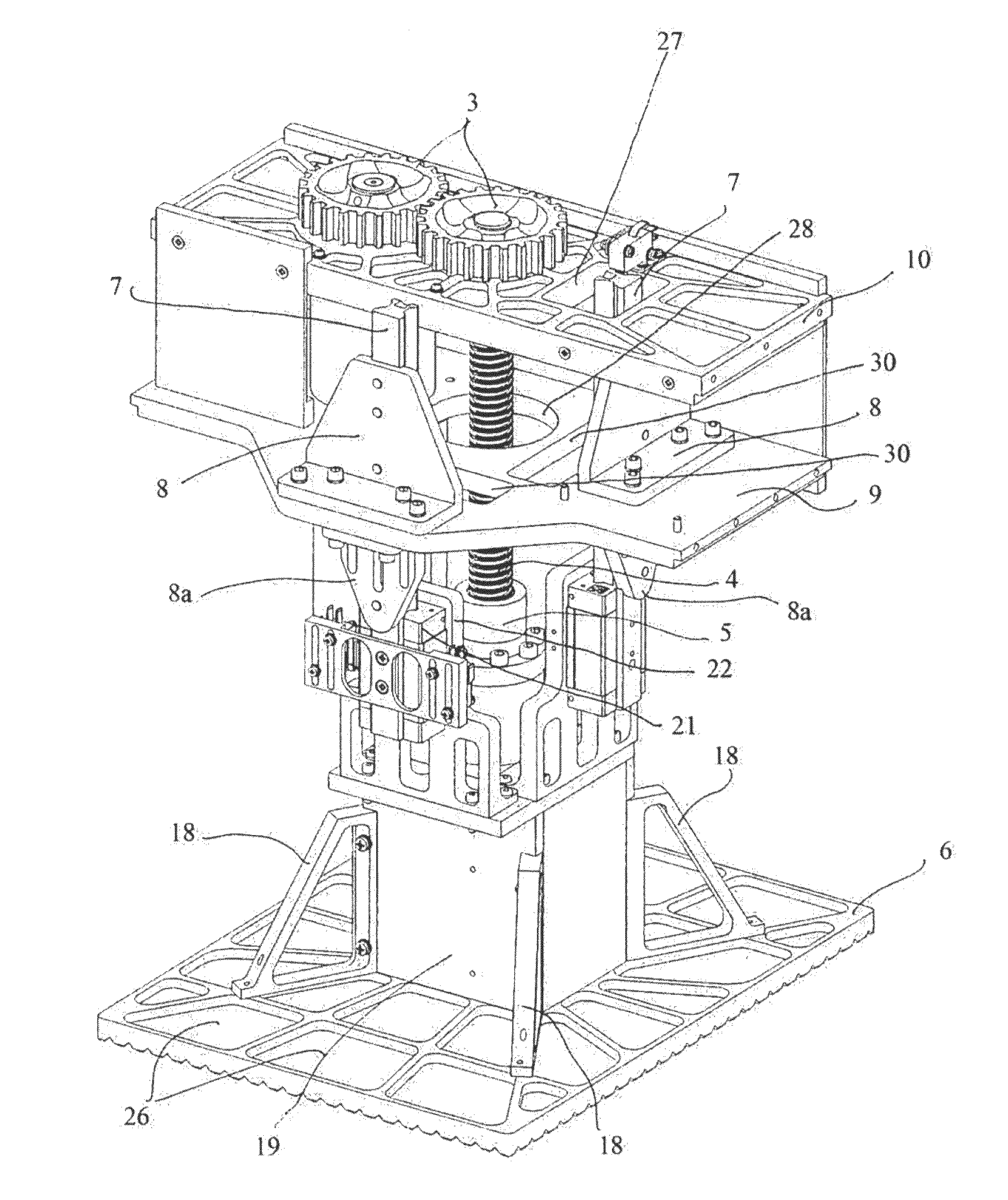
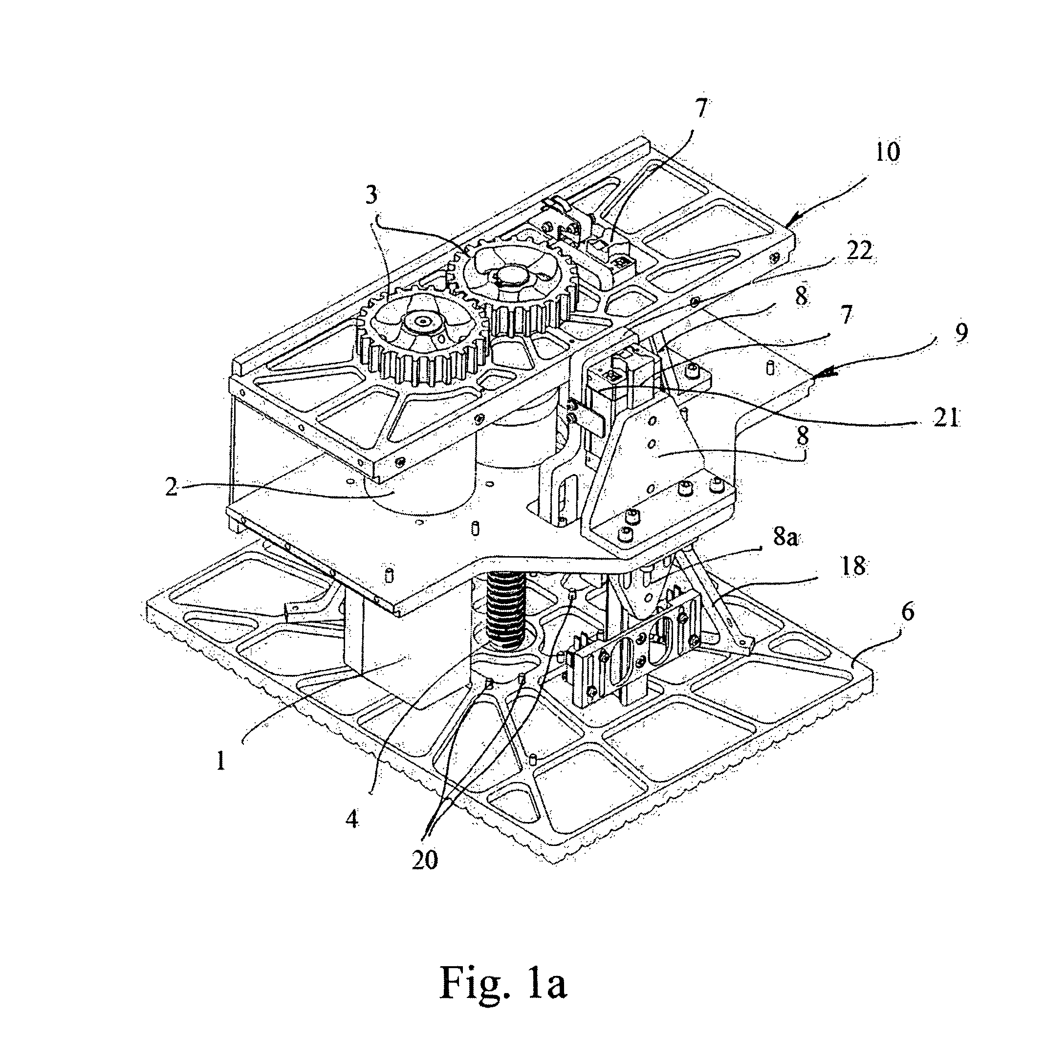
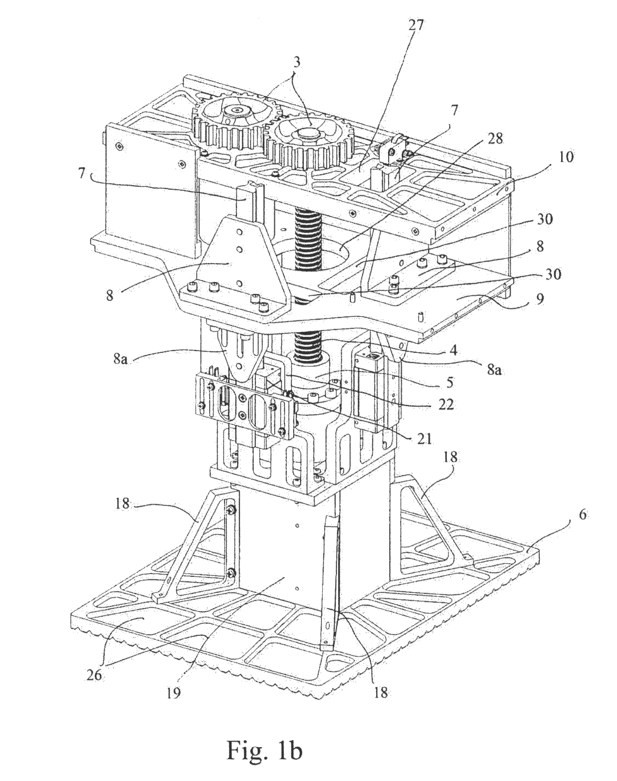
[0029]With reference to the appended FIGS. 1-4c, an embodiment of the waste compaction device of the invention is shown.

[0030]This waste compaction device comprises a fixed part and a mobile part.

[0031]The fixed part is preferably made with two superimposed horizontal supporting plates 9 and 10, with a space between them, and comprises an electro-mechanical device able to generate a rotary motion, typically an electric engine or rotary actuator 1 associated with a motor reducer 2 and at least a track or rail 7 fixed to its supporting elements 8, 8a and able to stabilize the movement of the mobile part. The rail passes inside the supporting plate 9 through an opening 30 and possibly through the supporting plate 10 in an opening 27.

[0032]To the shaft of the motor reducer 2 a first cogwheel 3 is fitted and engaged to a second cogwheel 3 fitted on an endless screw 4.

[0033]The endless screw 4, passing through an opening 28 obtained in the supporting plate 9, rotates inside a single nut w...


PUM


Abstract

Provided are electro-mechanical waste compactors which can operate also with 28 V power and of particularly reduced dimensions and weight. Provided are waste compaction devices which can be employed for civil uses, auxiliary service equipment, as, for example, trains, ships and vessels in general, aircrafts, coaches, caravans etc. Provided are compaction devices that can be conveniently installed in appropriate bays, fixed or movable on wheels, such as a trolley, to allow its ease of movement, and its insertion in the appropriate service spaces.

Description

[0001]This application is a national phase patent utility filing under 35 USC §371, for international application no. PCT / IT2010 / 000406, filed on 24 Sep. 2010, which claims the benefit of priority to Italian patent application serial no. RM 2009 A 000490, filed 25 Sep. 2009. The aforementioned applications are explicitly incorporated herein by reference in their entirety and for all purposes.FIELD OF THE INVENTION[0002]Provided are electro-mechanical waste compactors which can work also at 28 V and is of particularly reduced dimensions and weight. Provided are devices for waste compaction which can be employed for use in non-mobile environments (in particular domestic environments, restaurants, hotels, canteens, hospitals, etc.) or mobile environments, for example on board of all the transportation means that require a great economy of space for the auxiliary service equipment, as trains, ships, aircrafts, coaches, caravans etc. Provided are compaction devices of the invention that ...

Claims


Application Information

Patent Timeline
Patent Type & Authority Patents(United States)
IPC IPC(8): B30B1/18B30B9/30B30B15/04
CPCB30B9/3064B30B1/18B30B9/3021B30B15/041
Inventor IACOBUCCI, LUCIO
Owner IACOBUCCI HF ELECTRONICS
Why Eureka
Try Eureka