Self-limiting vacuum nozzle and methods for using same

a self-limiting, vacuum nozzle technology, applied in the direction of vacuum cleaners, cleaning processes and utensils, chemistry apparatus and processes, etc., can solve the problems of significant hazards to human life and health associated with combustible dust and work practices, and the removal of combustible dust is known in the art to be dangerous, so as to achieve enhanced control of the ingestion rate of combustible dust

Inactive Publication Date: 2015-07-28
BOLTUS GREGORY
View PDF14 Cites 0 Cited by
  • Summary
  • Abstract
  • Description
  • Claims
  • Application Information

AI Technical Summary

Benefits of technology

[0012]In another embodiment, SLV nozzle further comprises a suction disc defining an opening, said suction disc positioned adjacent to the suction port. In another embodiment, the SLV nozzle further incorporates a screen adjacent to the suction tube assembly that restricts the inadvertent ingestion of carbon steel hardware that might otherwise cause a spark in the vacuum system.
[0013]Another embodiment of the invention provides a vacuum system for removing combustible dust comprising a vacuum source; a self-limiting nozzle operatively connected to the vacuum source by a vacuum hose, the self-limiting nozzle comprising a nozzle body having a nozzle inlet port, a nozzle unloader port, and a suction port coupled to the vacuum hose; a suction tube assembly operably connected to the nozzle inlet port; the nozzle body adapted to receive a nozzle unloader disc adjacent to the nozzle unloader port, said nozzle unloader disc defining an opening of a selectable size, whereby the size of the opening in the unloader disc is selected to control the rate at which the combustible dust is ingested by the vacuum system to maintain the concentration of combustible dust within the vacuum hose at a level below the minimum explosive concentration of the combustible dust.
[0018]In another embodiment of the invention, the method further includes the step of controlling the rate of ingestion of combustible dust through the suction port by inserting a suction disc adjacent to the suction port. In another embodiment, the step of controlling the rate of ingestion of combustible dust is enhanced by providing the suction tube assembly unloader ports in the suction tube assembly. In another embodiment of the invention, the method further comprises the step of providing a vacuum hose that includes a conductive element which is bonded to ground. In another embodiment, the vacuum source is a truck-mounted, high flow rate vacuum source.

Problems solved by technology

The removal of combustible dust is known in the art to be dangerous, as combustible dusts have a Minimum Explosive Concentration (MEC) which cannot be exceeded within the equipment being used to remove the dust without the risk of explosion.
There are thus significant hazards to human life and health associated with combustible dusts and work practices.

Method used


Image

  • Self-limiting vacuum nozzle and methods for using same
  • Self-limiting vacuum nozzle and methods for using same
  • Self-limiting vacuum nozzle and methods for using same

Examples


example 1

6.1 Example 1

Components of the Self-Limiting Vacuum (SLV) Nozzle

[0094]In various embodiments, the SLV nozzle can comprise:

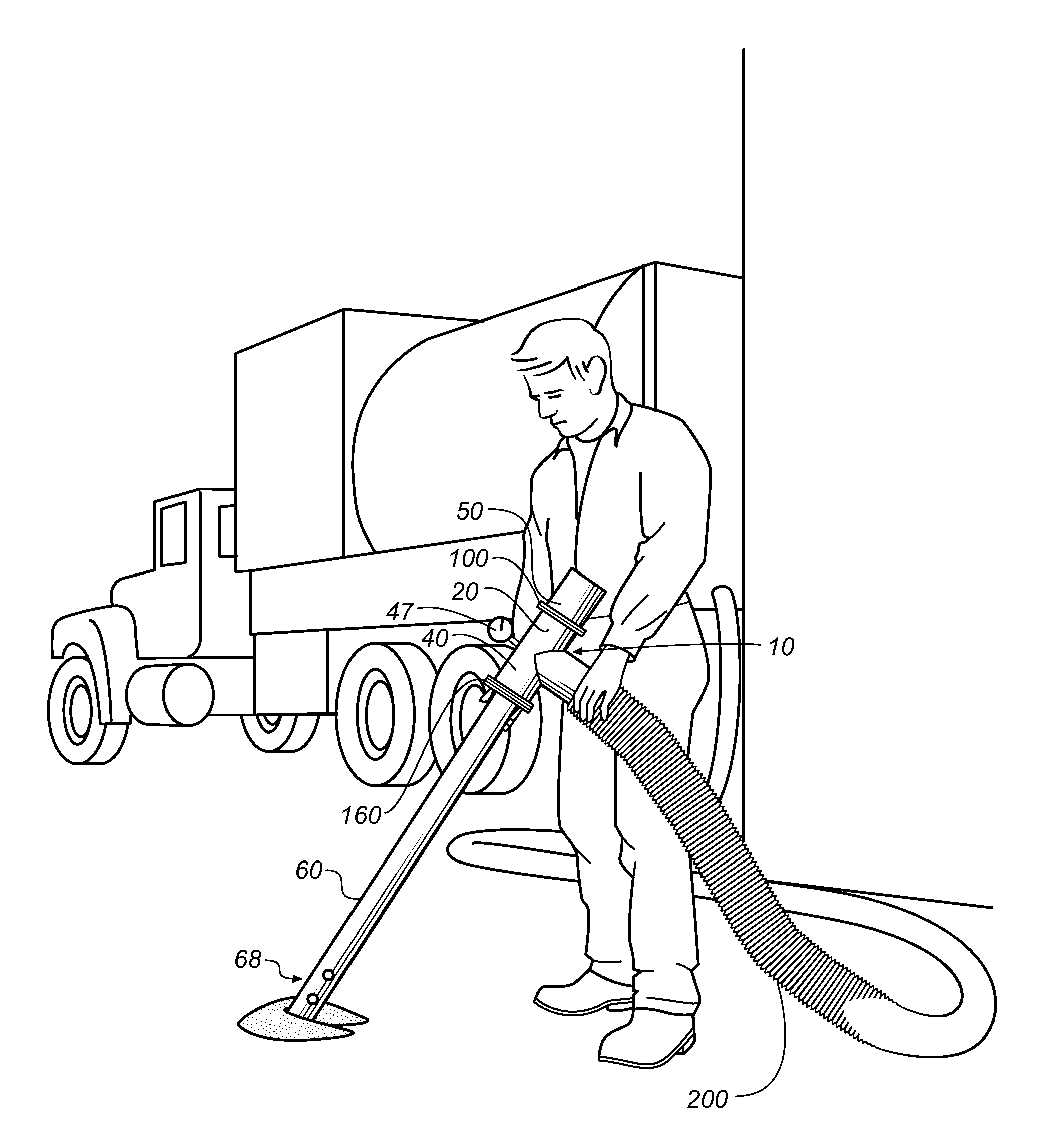
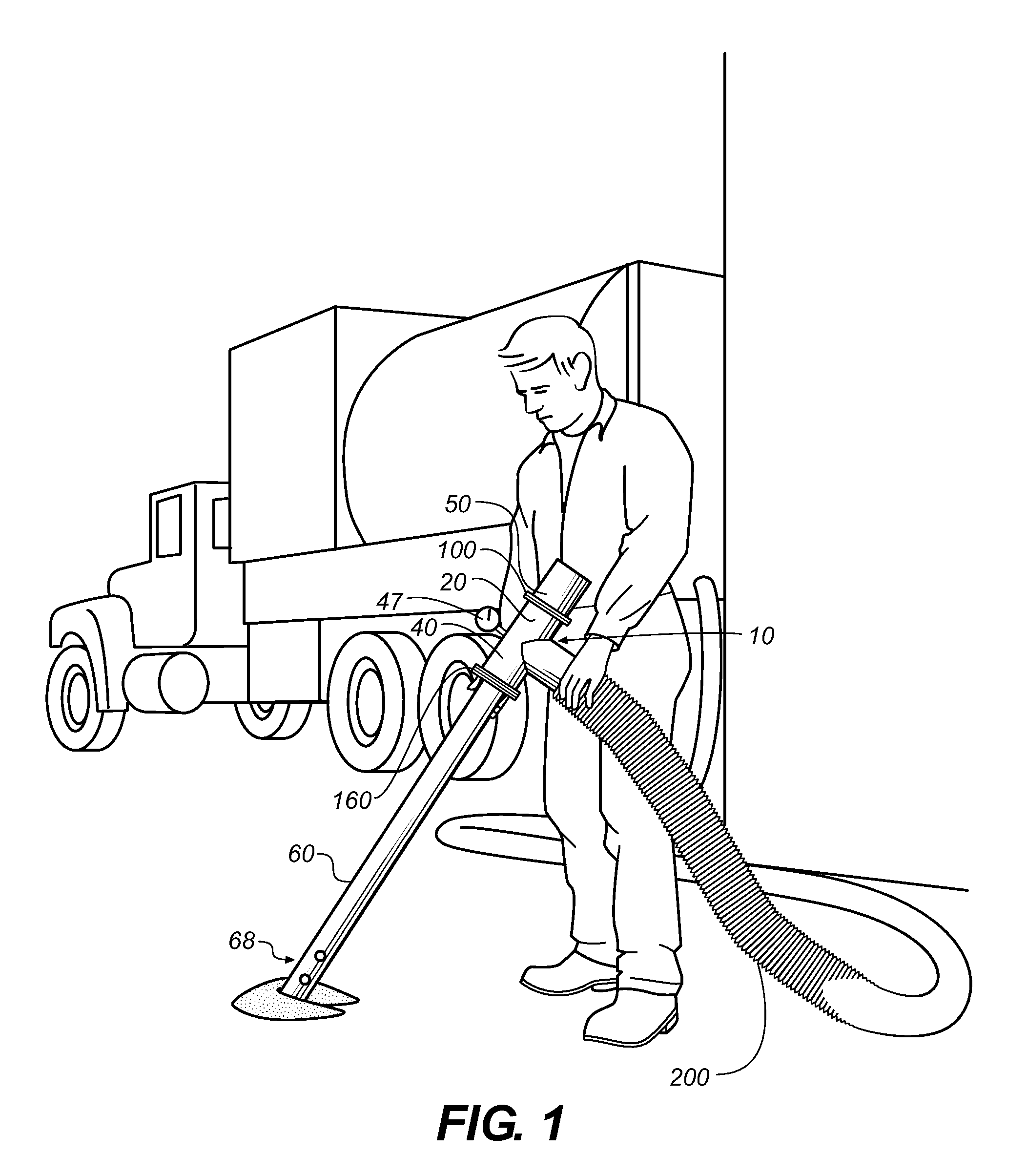
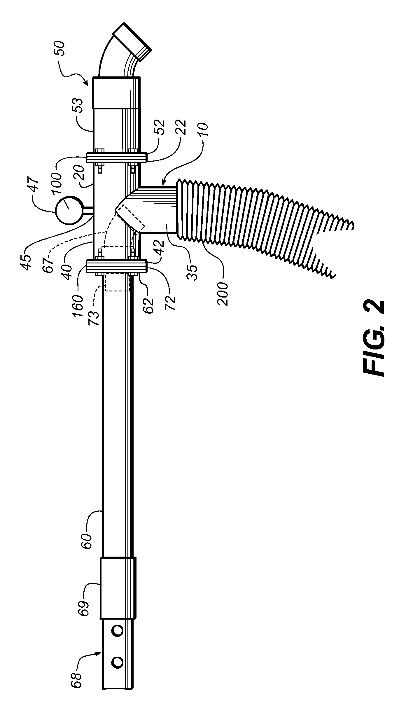
[0095]SLV Nozzle 10 Components:[0096]A. SLV body 11 (also referred to herein as a nozzle body) (FIGS. 1, 2, 6, 8 and 9)[0097]B. Suction disc(s) 160 (FIGS, 6-7)[0098]C. Unloader disc(s) 100 (can be used interchangeably with suction disc(s)[0099]D. Unloader 50 at unloader port 20 (FIGS. 1-3 and 6).[0100]E. Suction tube assembly 60 (FIGS. 1-3, 6, 10, 11) with suction tube assembly unloader ports (holes) 68[0101]F. Protective screen or cage over the unloader hood

[0102]Suction Tube Assembly 60 Components:[0103]A. Suction tube 61[0104]B. Suction tube flow reducer 66 (FIGS. 4-5) mounted on the distal (pick up) end of the suction tube assembly 60[0105]C. Screen or cage to prevent collection of small metal parts such as screws, nuts, and pins.

example 2

6.2 Example 2

Dry Vacuuming Using the SLV Nozzle

[0106]This example demonstrates the use of the SLV nozzle disclosed herein for dry vacuuming to remove accumulations of combustible dust (e.g., aluminum dust) from facility surfaces. To safely convey the dust generated from scalping operations, NFPA® 484 requires that the vacuum hose be maintained safely below the minimum explosive concentration (MEC) of 0.04 oz / ft3. Preferably, the MEC is determined from a Material Safety Data Sheet (MSDS) for the material to be collected or other MEC reference known in the art.

[0107]As typically used, the vacuum source air flow is essentially constant, but the volume of dust entering the vacuum nozzle inlet can vary widely, depending on the conditions in the facility from which the combustible dust is to be removed. For example, the quantity of dust entering the vacuum hose may be low when vacuuming a broom cleaned surface, but may spike sharply if a pocket or pile of dust is encountered that was inac...


PUM


Abstract

A self-limiting vacuum (SLV) nozzle is provided for collecting or removing combustible dust. The nozzle comprises a nozzle body comprising a nozzle inlet port, a nozzle unloader port, and a suction port; a suction tube assembly operably connected to the nozzle inlet port; a material deflector for directing vacuumed material from the suction tube assembly into the suction port; and an unloader hood installed in the unloader port. Discs can be installed in the unloader or suction port to control collection of combustible dust by the nozzle so that the concentration of dust collected within the hose stays below the minimum explosive concentration (MEC). The nozzle is operably connected to a vacuum source. Systems and methods for collecting combustible dust using the nozzle and a vacuum system are provided. Operation of the nozzle regulates the MEC of the combustible dust that is collected in the vacuum system.

Description

CROSS-REFERENCE TO RELATED APPLICATIONS[0001]This application claims priority to and the benefit of co-pending U.S. provisional patent application Ser. No. 61 / 550,139, entitled Self-Limiting Vacuum Nozzle and Methods for Using Same, filed Oct. 21, 2011, which is incorporated herein by reference in its entirety.STATEMENT REGARDING FEDERALLY SPONSORED RESEARCH OR DEVELOPMENT[0002]Not applicable1. Technical Field[0003]The present invention relates to devices and methods for cleaning fine, dry, particulate matter such as combustible dust by use of a vacuum system incorporating a self-limiting vacuum nozzle.2. Background of the Invention[0004]The removal of combustible dusts or powders from industrial structures has been an important service for many years. The removal of combustible dust is known in the art to be dangerous, as combustible dusts have a Minimum Explosive Concentration (MEC) which cannot be exceeded within the equipment being used to remove the dust without the risk of exp...

Claims


Application Information

Patent Timeline
Patent Type & Authority Patents(United States)
IPC IPC(8): B08B5/04A47L9/02
CPCB08B5/04A47L9/02
Inventor BOLTUS, GREGORY
Owner BOLTUS GREGORY
Why Eureka
Try Eureka