CMC ply overlap ingestion restrictor

a technology of restrictors and ply overlap, which is applied in the direction of machines/engines, sustainable transportation, climate sustainability, etc., can solve the problems of internal engine parts being exposed to excessive temperatures, structures not being as effective as desired in preventing hot gas ingestion

Active Publication Date: 2021-12-07
GENERAL ELECTRIC CO
View PDF5 Cites 2 Cited by
  • Summary
  • Abstract
  • Description
  • Claims
  • Application Information

AI Technical Summary

Benefits of technology

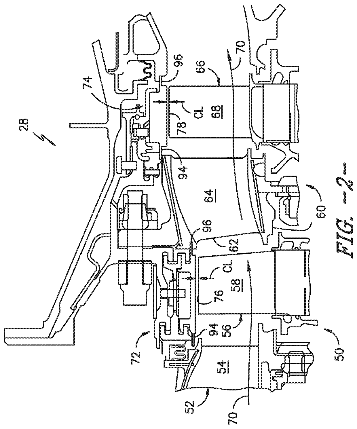
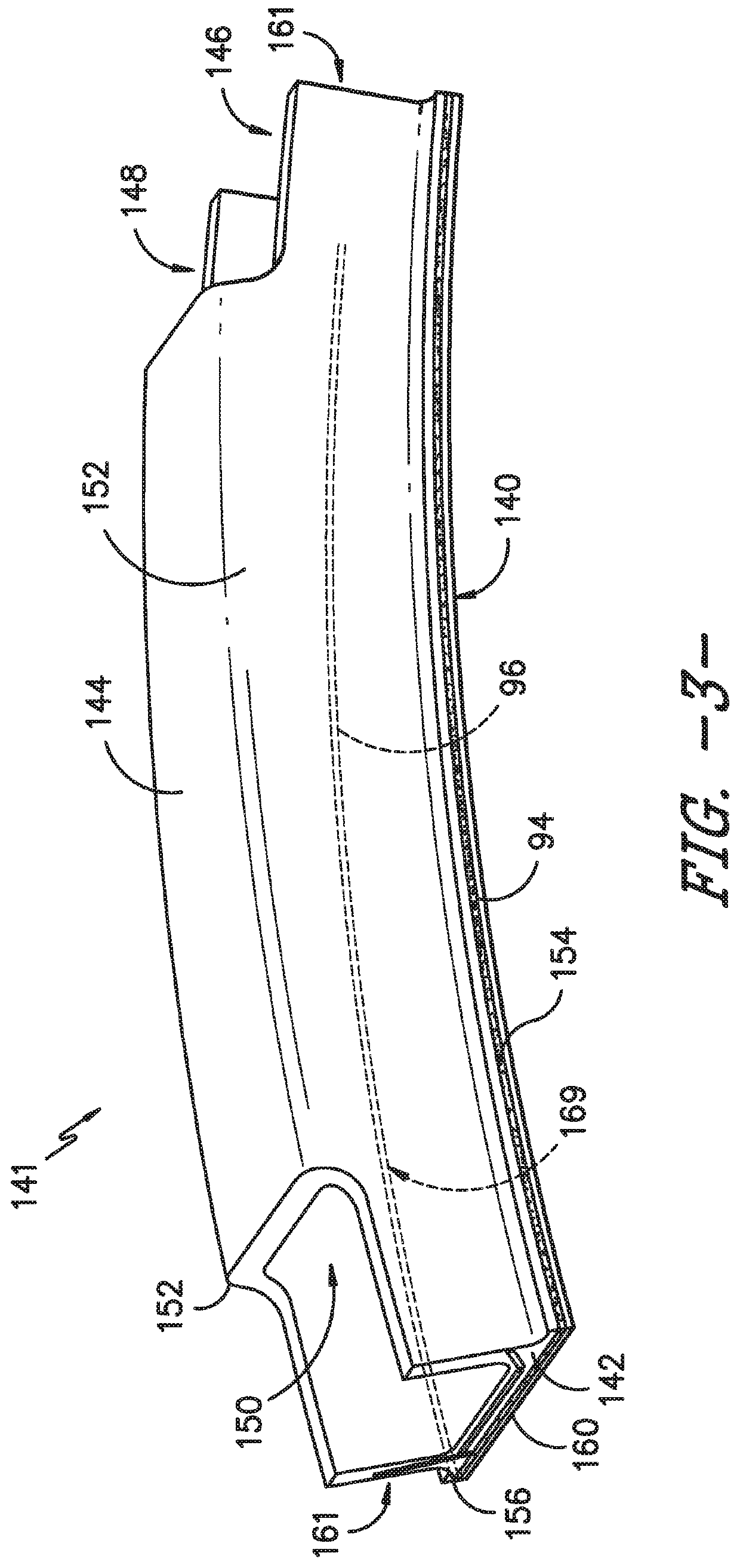
[0010]Methods are also generally provided for restricting ingestion of hot gas in a gas turbine engine. In one embodiment, the method includes laying up plies to form a ceramic matrix composite (CMC) first component having an integral protrusion from a first edge thereof, and positioning the CMC first component adjacent a second component having a second edge thereby defining a gap between the first edge and the second edge. The integral protrusion in the CMC first component extends from the first edge a distance sufficient to traverse the gap and to overlap the second edge of the second component thereby restricting ingestion through the gap.

Problems solved by technology

However, should a crack or bolt failure occur, the shroud may become disconnected from the shroud hanger.
As a result, internal engine parts are exposed to excessive temperatures.
These structures have not been as effective as desired in preventing hot gas ingestion.

Method used


Image

  • CMC ply overlap ingestion restrictor
  • CMC ply overlap ingestion restrictor
  • CMC ply overlap ingestion restrictor

Examples


Embodiment Construction

[0020]Reference now will be made in detail to embodiments of the invention, one or more examples of which are illustrated in the drawings. Each example is provided by way of explanation of the invention, not limitation of the invention. In fact, it will be apparent to those skilled in the art that various modifications and variations can be made in the present invention without departing from the scope or spirit of the invention. For instance, features illustrated or described as part of one embodiment can be used with another embodiment to yield a still further embodiment. Thus, it is intended that the present invention covers such modifications and variations as come within the scope of the appended claims and their equivalents.

[0021]As used herein, the terms “first”, “second”, and “third” may be used interchangeably to distinguish one component from another and are not intended to signify location or importance of the individual components.

[0022]The terms “upstream” and “downstre...


PUM


Abstract

An ingestion restricting device is provided, which is particularly useful in a turbine engine. The ingestion restricting device can include a first component defining a first edge and including a plurality of ceramic matrix composite (CMC) plies forming outer, inner, and intermediate layers. The ingestion restricting device can also include a second component adjacent to the first component and defining a second edge. The first edge of the first component is opposite the second edge of the second component and defines a gap therebetween. Also, at least one ply of the plurality of CMC plies in the outer layer of the first component comprises an integral protrusion extending from the first edge a distance sufficient to traverse the gap and to overlap the second edge of the second component.

Description

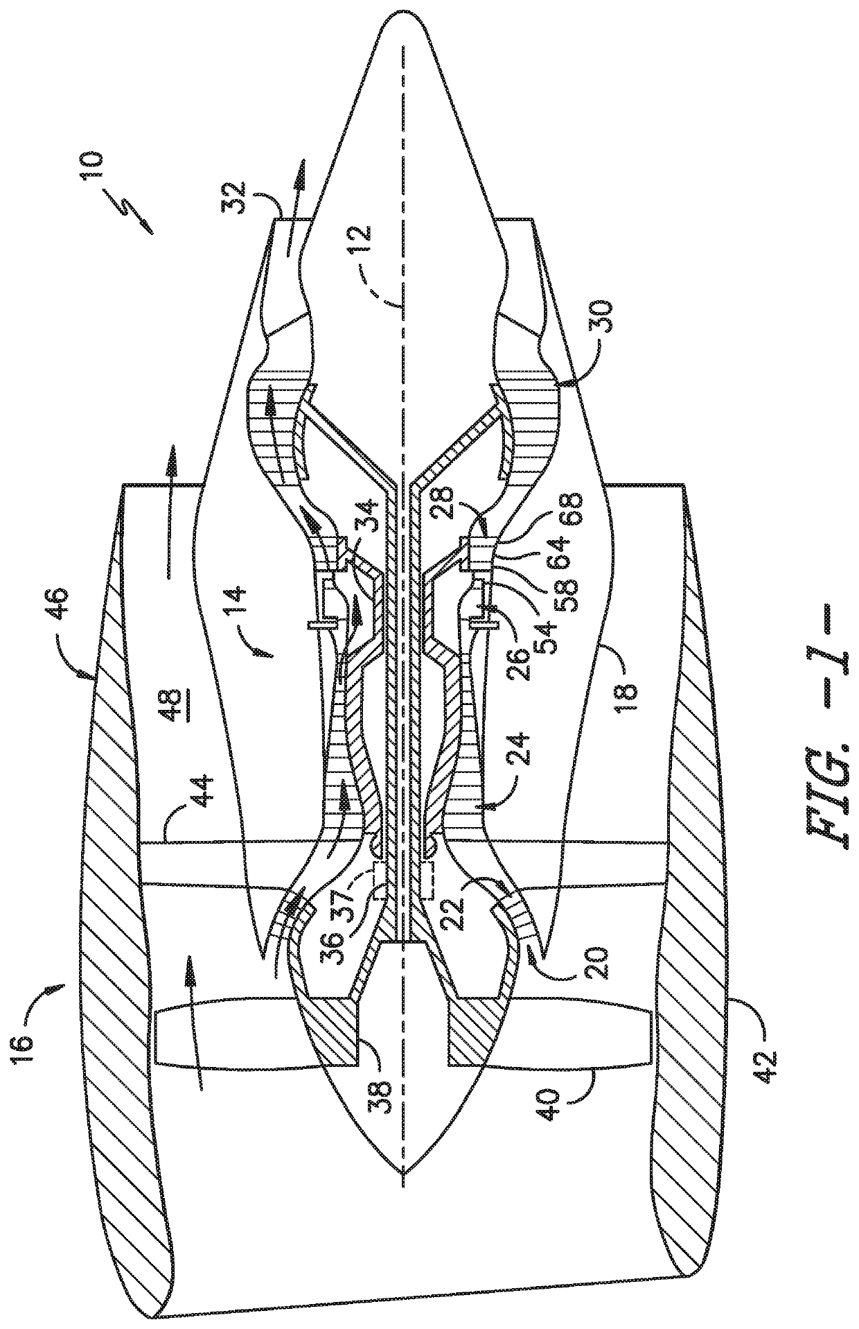
FIELD OF THE INVENTION[0001]The present disclosure generally pertains to adjacent components of gas turbine engines that have a gap therebetween. More particularly, but not by way of limitation, present embodiments relate to ceramic matrix composite (CMC) shrouds and adjacent components utilized in gas turbine engines that can experience hot gas ingestion in the gap.BACKGROUND OF THE INVENTION[0002]A typical gas turbine engine generally possesses a forward end and an aft end with its several core or propulsion components positioned axially therebetween. In operation, air is pressurized in a compressor and mixed with fuel in a combustor for generating hot combustion gases which flow downstream through turbine stages. These turbine stages extract energy from the combustion gases. A high pressure turbine first receives the hot combustion gases from the combustor and includes a stator nozzle assembly directing the combustion gases downstream through a row of high pressure turbine rotor ...

Claims


Application Information

Patent Timeline
Patent Type & Authority Patents(United States)
IPC IPC(8): F01D25/00F01D25/24F01D11/02
CPCF01D25/246F01D11/02F05D2240/11F05D2300/6033Y02T50/60
Inventor FREY, DAVID ALAN
Owner GENERAL ELECTRIC CO
Why Eureka
Try Eureka