Bottom mount blade positioning assembly for a motor grader

a technology of motor graders and positioning parts, which is applied in the direction of mechanical machines/dredgers, soil-shifting machines/dredgers, constructions, etc., can solve problems such as impaired visibility, and achieve the effect of more visibility

Active Publication Date: 2015-08-04
DEERE & CO
View PDF16 Cites 2 Cited by
  • Summary
  • Abstract
  • Description
  • Claims
  • Application Information

AI Technical Summary

Benefits of technology

[0006]The present invention provides a blade positioning assembly that is mounted to the underside of the main frame. A pivot member in the form of a mounting ring is attached to the bottom of the main frame. A blade lift member is attached to the bottom of the mounting ring to keep the blade lift member in line with the axle and thereby allow for more visibility around the blade lift member, front axle and tires.

Problems solved by technology

Visibility is impaired with a blade positioning linkage that wraps completely around the main frame.

Method used


Image

  • Bottom mount blade positioning assembly for a motor grader
  • Bottom mount blade positioning assembly for a motor grader
  • Bottom mount blade positioning assembly for a motor grader

Examples


Embodiment Construction

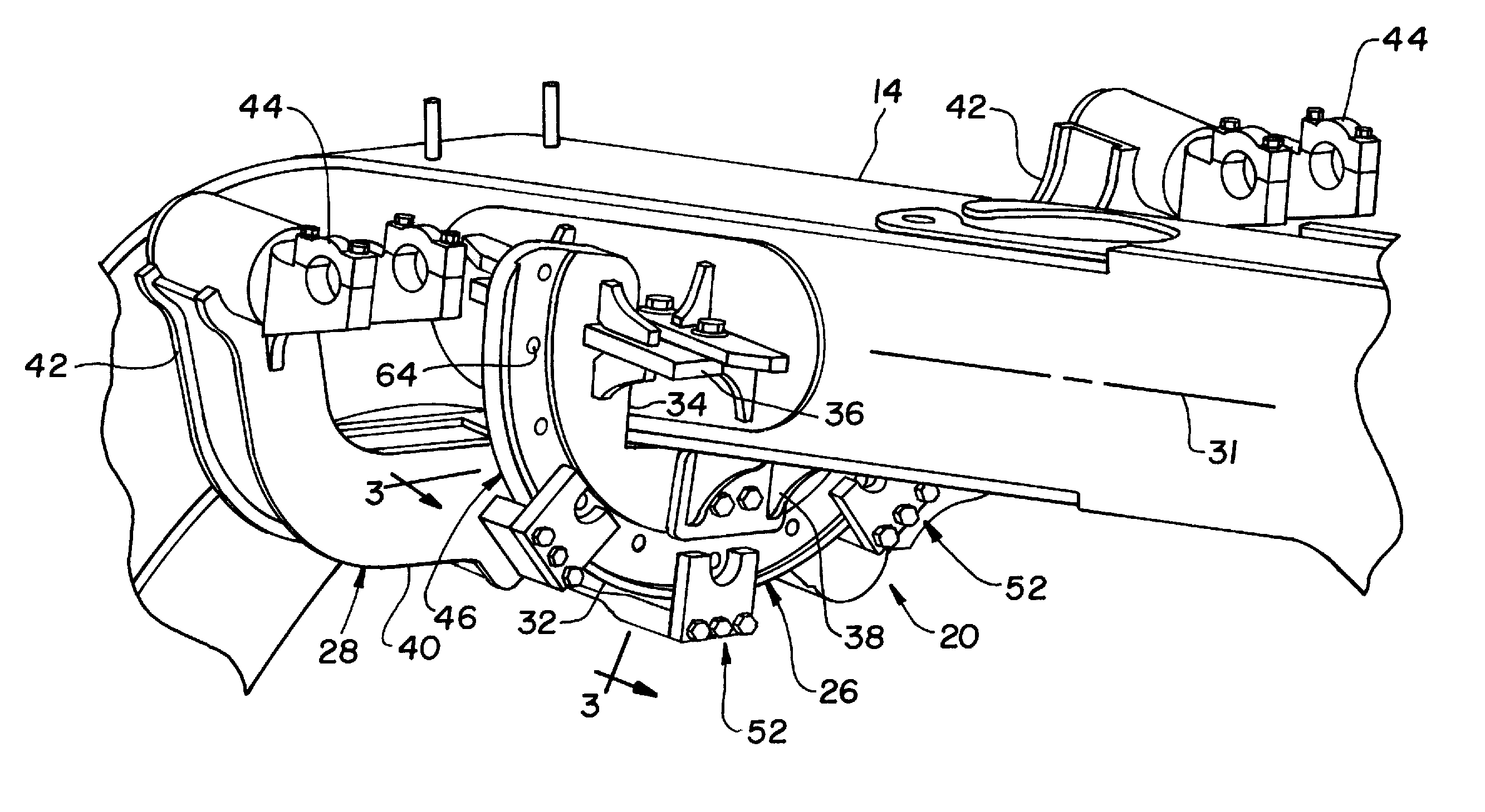
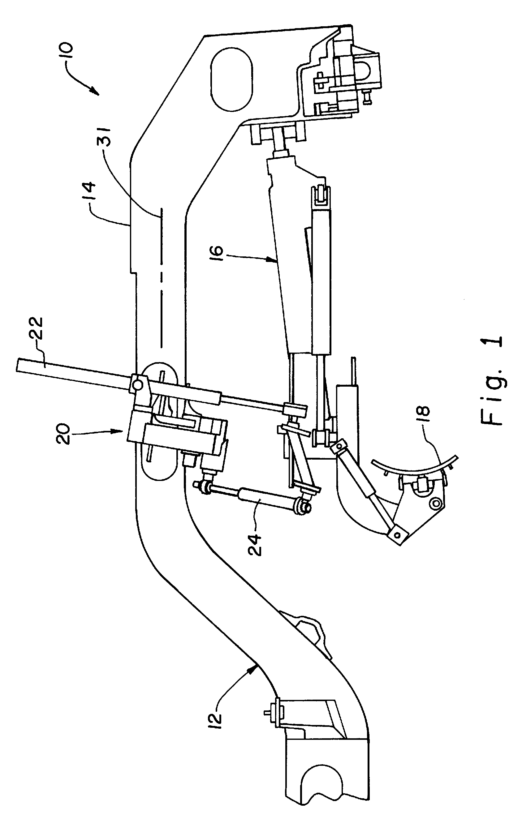
[0017]Referring now to the drawings, and more particularly to FIGS. 1 and 2, there is shown a portion of a motor grader 10 which includes a base unit 12 having a longitudinally extending main frame 14 which supports an operator cab, engine compartment, transmission, and wheels (not visible). Main frame 14 also supports a circle drive arrangement 16, moldboard blade 18 and blade positioning assembly 20. A pair of blade lift cylinders 22 interconnect blade positioning assembly 20 with circle drive arrangement 16 and effect selective up-and-down movement of either end of blade 18. A lateral shift cylinder 24 also interconnects blade positioning assembly 20 with circle drive arrangement 16 and effects selective lateral side-to-side movement of blade 18.

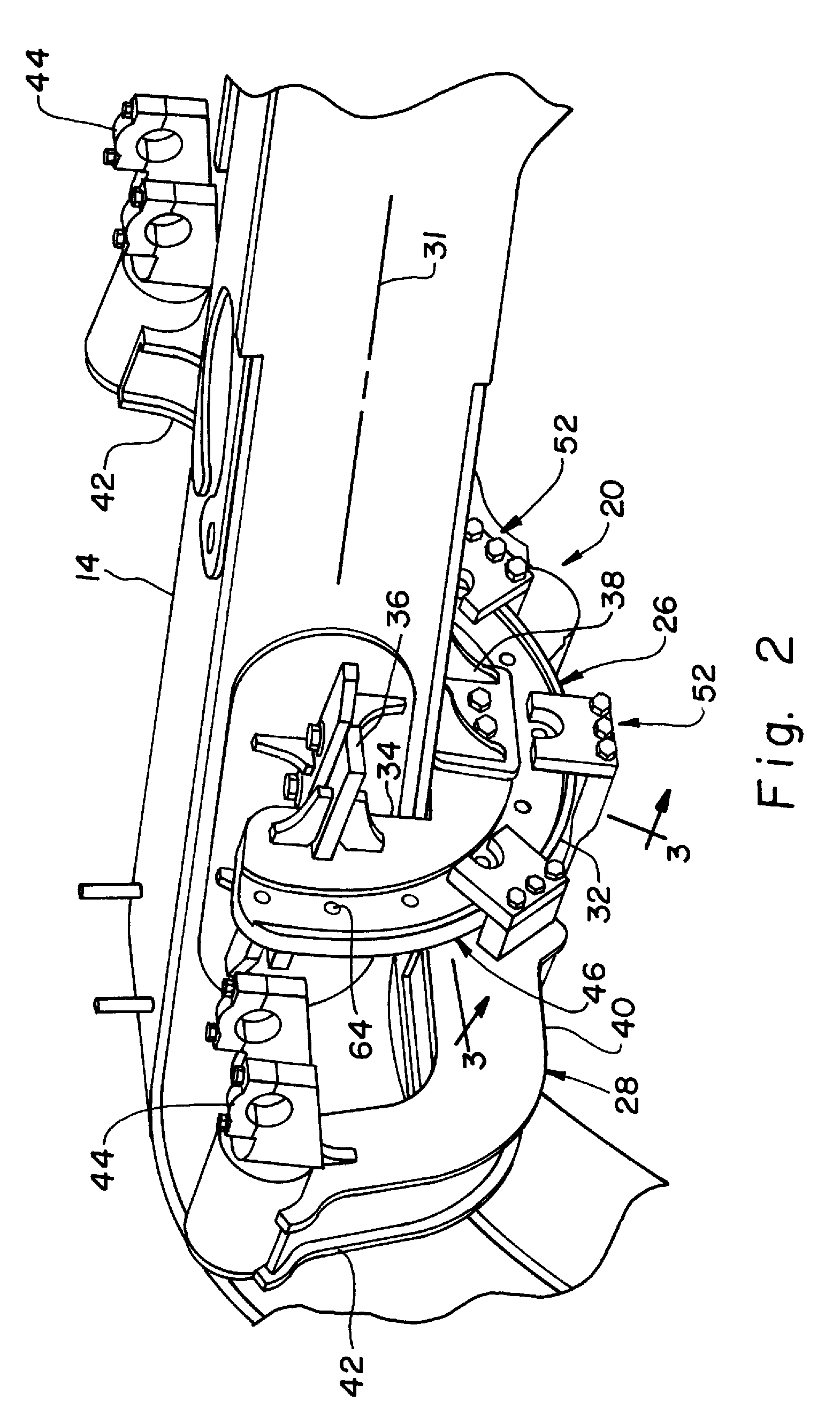
[0018]Referring now to FIGS. 2-5, blade positioning assembly 20 will be described in greater detail. Blade positioning assembly 20 generally includes a pivot member 26 and blade lift member 28. Pivot member 26 is directly attached to the ...


PUM


Abstract

A motor grader includes a base unit and a blade positioning assembly. The base unit has a main frame. The blade positioning assembly includes a pivot member attached to and extending downwardly from the main frame, and a blade lift member attached to a bottom end of the pivot member.

Description

FIELD OF THE INVENTION[0001]The present invention relates to motor graders, and, more particularly, to blade positioning linkages used with such motor graders.BACKGROUND OF THE INVENTION[0002]A motor grader is used to rough or finish grade an earth surface and includes a base unit with a main frame supporting traction wheels, operator cab, engine compartment, transmission, and a belly mounted (moldboard) blade. The blade extends downwardly from a circle drive arrangement which adjusts the angular orientation of the blade relative to a generally vertical axis. The circle drive arrangement is movably connected with the main frame at the front end. A blade positioning linkage attached to the main frame interconnects with the rear of the circle drive arrangement via a pair of blade positioning cylinders.[0003]When using a motor grader it is important to have as much visibility as possible to and around the front axle and tires, as well as the blade. A blade positioning linkage having de...

Claims


Application Information

Patent Timeline
Patent Type & Authority Patents(United States)
IPC IPC(8): E02F3/76
CPCE02F3/7672E02F3/7677E02F3/7681E02F3/765E02F3/76
Inventor STAADE, DUSTIN T.HARBER, NEIL V.HORSTMAN, NATHAN J.
Owner DEERE & CO
Why Eureka
Try Eureka