Mounting Device with Mirror-Image Mounting Surfaces

a mounting device and mirror image technology, applied in the field of mounting, can solve the problems pressure applied to the junction of surfaces, and incur the risk of damage to the object, so as to achieve the effect of less damage risk and more visibility of the object s

Inactive Publication Date: 2015-02-26
CARTER NICK PAUL +2
View PDF1 Cites 0 Cited by
  • Summary
  • Abstract
  • Description
  • Claims
  • Application Information

AI Technical Summary

Benefits of technology

[0020]It is an object of the invention to provide a new and improved mounting for an object which allows more visibility of an object set within a mounting.
[0021]It is an object of the invention to provide a new and improved mounting for objects which allows skilled industry workers to set an object more securely and with less risk of damaging the object during the setting process.

Problems solved by technology

Pressure applied at surface junctions during setting can cause damage to the object.
However, this approach can still result in pressure applied to a junction of surfaces.
This method achieves a finished article in fewer steps than other procedures, but still incurs risk of damage to the object during the casting process, and is difficult to use with some gemstones which cannot withstand the heat required in the casting process.
Further, this method does not allow tolerance in the mounting and does not result in mounting surfaces within seats which mirror the surfaces of the object within the mounting.
When points of contact do not exactly match the shape of the object, it is more difficult to securely set in an object in a mounting.
This can lead to an object becoming loose within a mounting or falling out of the mounting, which can result in loss of or damage to an object, and such damage can result in significantly reduced value of an object.
Damage can also occur if an article is dropped, because the points of contact can transfer impact pressure similar to that which occurs during setting.
Such a bezel requires pressure against the gemstone during setting, risking damage.
However, in most invisible settings the object must be notched or grooved below the pavilion, which alters the original shape of the object, reducing the weight and therefore potentially the value of the object.

Method used


Image

  • Mounting Device with Mirror-Image Mounting Surfaces
  • Mounting Device with Mirror-Image Mounting Surfaces

Examples


illustration 1

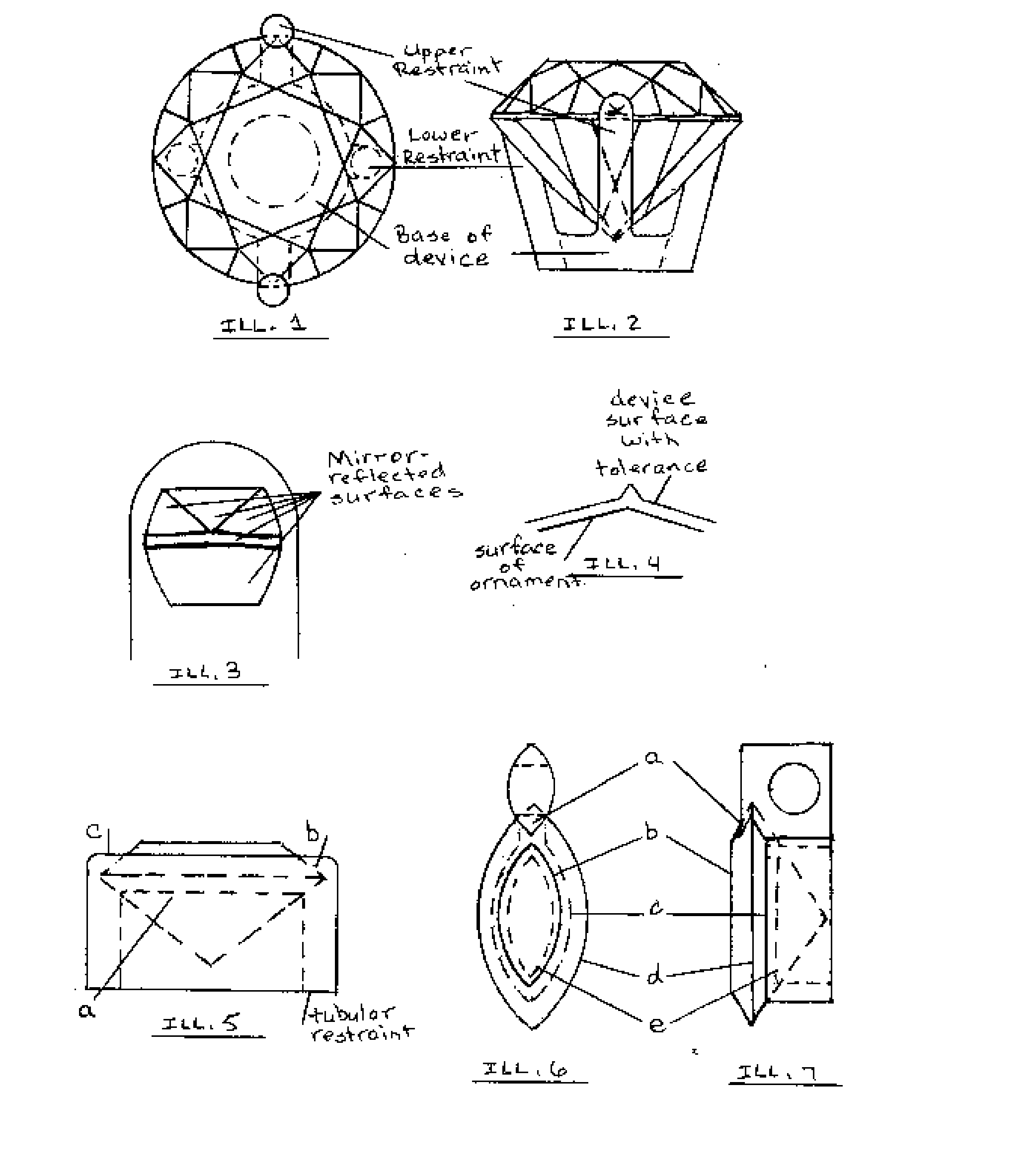
[0040]Illustration 1 shows the top elevation of the claimed invention in its preferred embodiment as a mounting for a gemstone to be worn as jewelry. This embodiment includes two visible upper restraints on the upper portion of the gemstone (the crown) and 4 hidden supports on the lower portion of the gemstone (the pavilion). As the supports are not visible in the top viewing position, they are illustrated in hidden lines in Illustration 1. Two of the lower supports connect with the visible upper restraints, to which they are structurally joined. Two of the lower supports, indicated by hidden lines in Illustration 1, do not join to upper restraints. The claimed invention requires at least one upper restraint and at least one lower support. The restraints and supports may be rib-like members as illustrated in this illustration, or might enclose the perimeter of an object, as illustrated by the tubular restraint in Illustration 5. Illustration 1 further illustrates, in hidden lines, t...
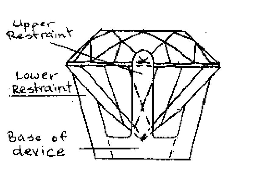
illustration 2

[0041]Illustration 2 shows the side elevation of the claimed invention in the same embodiment as Illustration 1. In Illustration 2, the upper restraints of Illustration 1 are visible, as well as the lower supports connected to said upper restraints. A portion of the gemstone is obstructed by the visible restraint / support combination, and that obstructed portion is shown in hidden lines in Illustration 2. The base of this embodiment is visible in Illustration 2. The restraints are constructed so as to lie in planes parallel to the planes of the gemstone. The facets of the gemstone define these planes.

[0042]Illustration 3 shows the mounting seat from one upper restraint of the invention as embodied in Illustrations 1 and 2, in which the invention utilizes prong-style restraints and supports to contain a round brilliant faceted gemstone. Illustration 3 illustrates that the inside mounting surfaces of the seat correspond to the shape and dimension of the gemstone to be displayed. In thi...

illustration 4

[0043]Illustration 4 shows one embodiment of tolerance in the claimed invention. The invention allows but does not require tolerance at any location where an object could incur stress from the pressure of the mounting. Such points include surfaces (facets) or junctions between surfaces (facet edges) on the displayed object. The tolerance avoids direct pressure by the mounting on surfaces or surface junctions and thus provides one of the main benefits of the claimed invention. The claimed invention may comprise such tolerance at any surface or at any point where object surfaces meet, including but not limited to crown facets, crown facet junctions, crown-to-girdle junctions, girdle-to-pavilion junctions, pavilion-to-culet junctions, and the culet. The exact shape and depth of tolerance is determined at the designer's discretion during the preferred manufacturing process. Tolerance may be allowed wherever two or more surfaces meet on the object.


PUM


Abstract

The claimed invention is a mounting device for an object. The preferred embodiment is as a jewelry device or display device. The mounting device comprises supports and restraints whose surfaces correspond precisely to selected surfaces on the object. Mounting surfaces allow tolerance with regard to interfit with the object. In the jewelry industry, the result is that the interior surfaces of seats in a mounting are the mirror image of facets on a gemstone. This use of reflected geometry in a mounting provides benefits in manufacturing, setting, and usage of a finished article. The mounting may be constructed of one or more than one piece, and those pieces may be permanently or temporarily joined to form the mounting. The mounting may be manufactured by any of several methods subject to a skilled designer's preference, including but not limited to fabrication by manual process, computer-aided design and manufacturing, metal-powder. The preferred method disclosed with this invention utilizes computer-aided design and machining (CAD/CAM).

Description

CROSS-REFERENCE TO RELATED APPLICATIONS[0001]This application claims the benefit of provisional application 61 / 693,060, “Device for holding ornamental objects,” filed Aug. 24, 2012STATEMENT REGARDING FEDERALLY SPONSORED RESEARCH OR DEVELOPMENT[0002]Not applicable. This invention was not made under federally sponsored research or development.REFERENCE TO SEQUENCE LISTING / TABLE / COMPUTER PROGRAM LISTING COMPACT DISC[0003]Not applicable. This invention does not require a sequence listing, table, or computer program.BACKGROUND OF THE INVENTION[0004]This invention relates generally to a mounting for objects to be worn as jewelry or displayed for visual observation, and particularly to a mounting device in which the mounting surfaces correspond in shape and dimension to the surfaces of the contained object. Several terms from the industry of designing, manufacturing, and assembling display devices and articles of jewelry apply to this invention: setting refers to the process of installing ...

Claims


Application Information

Patent Timeline
Patent Type & Authority Applications(United States)
IPC IPC(8): A44C17/02G05B19/4097F16M11/02
CPCA44C17/02G05B19/4097F16M11/02G05B2219/35069G05B2219/35118Y02P90/02
Inventor CARTER, NICK PAULCARTER, BETHANY BENNETTCARTER, LOGAN BENNETT
Owner CARTER NICK PAUL
Why Eureka
Try Eureka