A pipeline padder

a pipeline padder and pad technology, applied in the direction of pipe laying and repair, pipe supports, pipe/joints/fittings, etc., can solve the problems of inability to use pipeline padder types, time-consuming process, and inability to redelivered material from the trenches on top of the pipes, etc., to achieve the effect of convenient or commercial choi

Inactive Publication Date: 2016-05-26
MURPHY PIPE & CIVIL IP
View PDF3 Cites 1 Cited by
  • Summary
  • Abstract
  • Description
  • Claims
  • Application Information

AI Technical Summary

Benefits of technology

[0007]It is an object of the invention to overcome and / or alleviate one or more of the above disadvantages and / or provide the consumer with a useful or commercial choice.

Problems solved by technology

However, in many instances, the specification of the pipeline does not allow the material that has been excavated from the trench to be redelivered on top of the pipes.
Therefore these types of pipeline padders are unable to be used when specific material, such as sand, is specified to cover pipes within the pipeline.
This is a very time consuming process.
Unfortunately these pipeline padders are unable to transport a large amount of particular material and the conveyor systems are often too light.
Further, if the particulate material is located in a remote location, a large number of vehicles are required to keep pace with the laying of pipe.
This is a large capital cost that may not be able to be recuperated in subsequent operations.

Method used


Image

  • A pipeline padder
  • A pipeline padder
  • A pipeline padder

Examples


Embodiment Construction

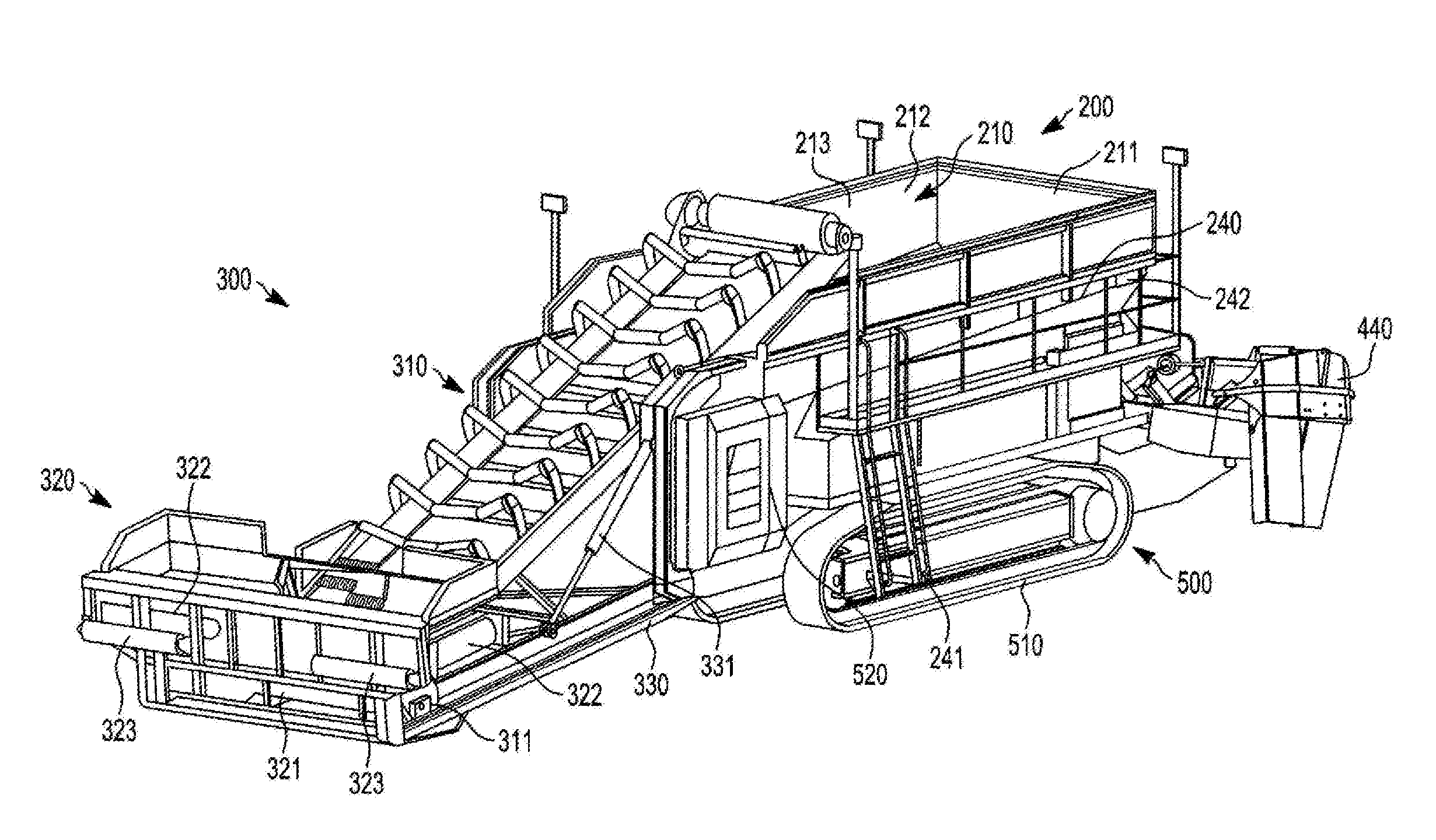
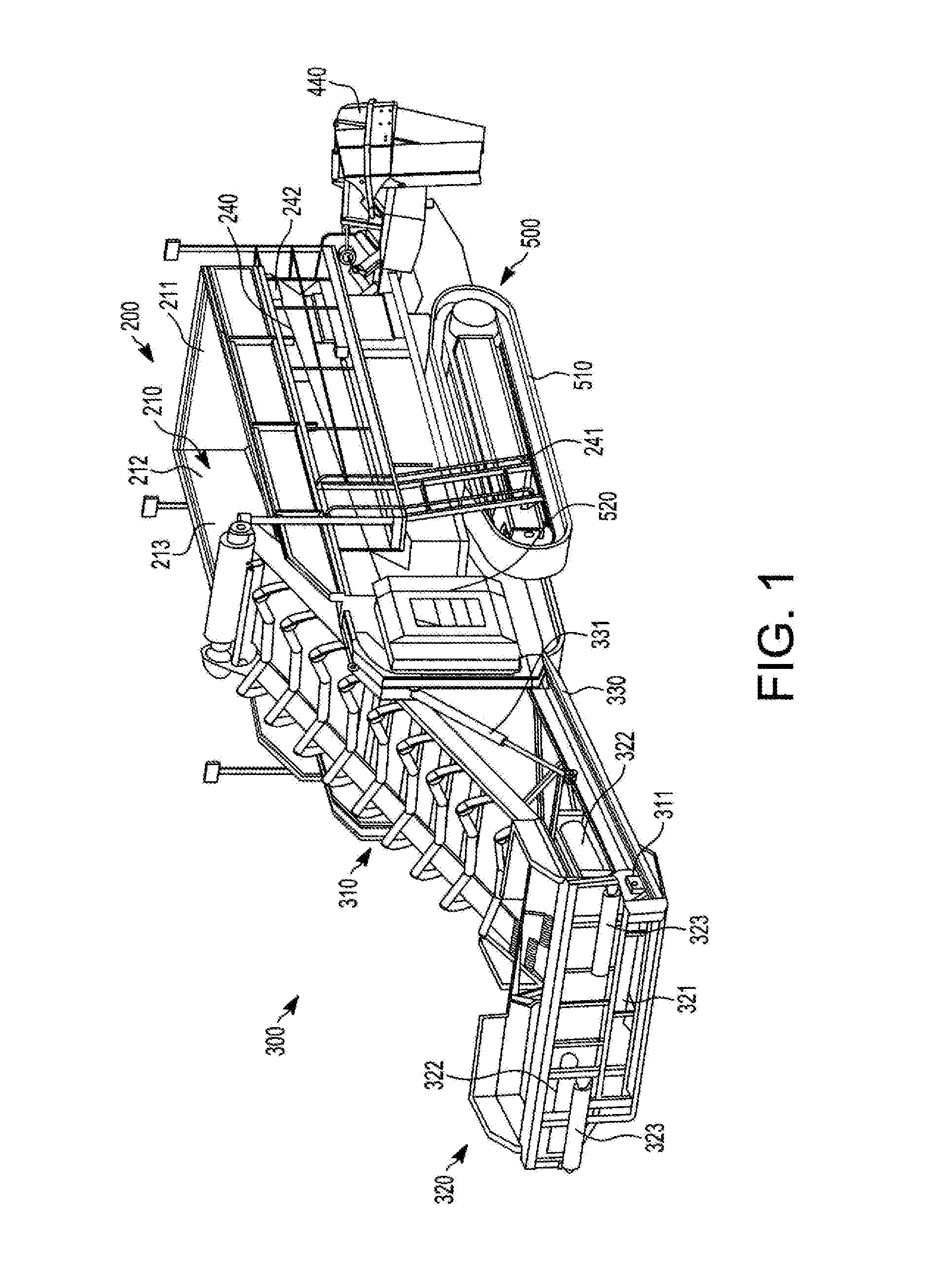
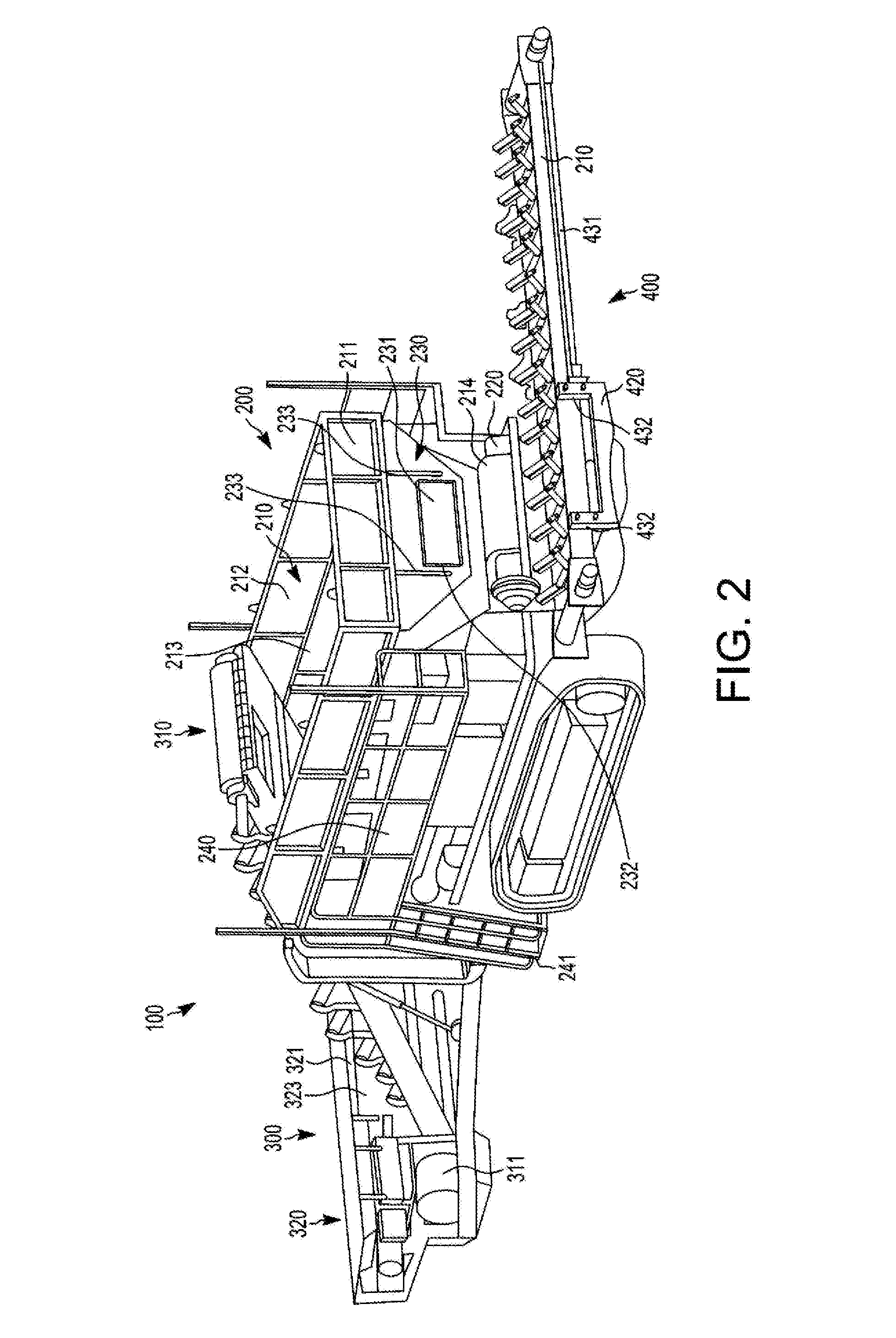
[0042]FIGS. 1 and 2 shows a pipeline padder 100 that it used to deliver fine particular materials such as sand into a trench to cover a pipeline. The pipeline padder 100 includes a storage unit 200, a loading unit 300, a discharge unit 400 and a locomotion unit 500.

[0043]The storage unit 200 includes a hopper 210 and a storage conveyor 220. The hopper 210 is used to store particular material such as sand. The hopper 210 includes two end walls 211 and two side walls 212. The two side walls 212 have a portion of the side wall 212 which is inclined. The inclination of the side wall 212 is approximately at 45 degrees. Both end walls 211 are substantially parallel to each other. The hopper has an open top 213. An exit 214 is located in an end wall 211 of the hopper 210.

[0044]The storage conveyor 220 forms the base of the hopper 210. Any particulate material that is located within the hopper 210 will slide down the inclined side walls 212 and sit on top of the storage conveyor 220. The st...


PUM


Abstract

A pipeline padder comprising: a storage unit including a hopper for storing particulate material and a storage conveyor to remove particulate material from the hopper; a loading unit including a loading conveyor to load particulate material into the hopper; a discharge unit including a discharge conveyor for discharging particular material supplied by the storage conveyor; and a locomotion unit to move the storage unit.

Description

FIELD OF THE INVENTION[0001]This invention relates to a pipeline padder. In particular the invention relates to a pipeline padder that is able to cover pipes with sand. However it should be appreciated that the pipeline padder may be used with other particulate materials such as gravel, blue metal or other aggregates.BACKGROUND OF THE INVENTION[0002]Pipelines are integral to most countries infrastructure. The technology surrounding the laying of pipes has increased dramatically over the years. This increase in technology has enabled pipes made of various materials to be laid very quickly. Accordingly it has been necessary to develop technology that enables pipes that have been laid to also be covered quickly and without damage. This has led to the development of pipeline padders.[0003]Pipeline padders are used to deliver particulate material to cover pipes both quickly and accurately. Some pipeline padders have been developed that screen the materials that have been excavated to for...

Claims


Application Information

Patent Timeline
Patent Type & Authority Applications(United States)
IPC IPC(8): E02F5/22E02F7/00F16L1/028F16L3/26F16L1/06F16L1/024
CPCE02F5/226F16L1/06F16L1/0243E02F7/00F16L3/26E02F5/223F16L1/028
Inventor DERMODY, THOMAS ROBERT
Owner MURPHY PIPE & CIVIL IP
Why Eureka
Try Eureka