
Operational mode sensing switch system and multi-oriented mounting system for a helmet mounted night vision device

Pending Publication Date: 2021-05-06
DESIGNWORKS DEFENCE SYST PTY LTD
View PDF0 Cites 4 Cited by
  • Summary
  • Abstract
  • Description
  • Claims
  • Application Information

AI Technical Summary

Benefits of technology

The present invention is a helmet mounting assembly for night vision goggles that solves the problem of difficulty in shutting off the goggles when stowed and activating them when returned to the in-use position. The assembly allows for automatic shutting off and activation, making the use of the goggles more convenient and efficient.

Problems solved by technology

Some devices utilise a magnetic switch in the semi-automatic shutdown, but these are limited in their operational aspects because, amongst other reasons, the user can falsely trigger the magnetic switch by looking up towards the sky while the ENVG is in the in-use position or by looking down when the ENVG is in the stowed position.
This is a considerable disadvantage as the user is unable to see with the ENVG while looking up beyond a certain angle.
It is also a disadvantage as the ENVG produces a viewable image by emitting visible light for the user when switched on and the user's position can be given away to the enemy when the ENVG is falsely turned on while in the stowed position on the user's helmet.
This is a particularly serious issue for soldiers using ENVG.
While known mounting assemblies try to overcome this issue with specially shaped cavities for a magnet to travel in, or electronic sensors placed within the ENVG, it can be difficult to automatically distinguish the operational mode (i.e. in-use or stowed) of the ENVG.
False activation of the switch can still occur if the user is required to look up or down beyond a preset angle.
While some mounting systems allow the ENVG to be mounted on the left or right side, often additional parts or tools are required to swap sides.

Method used


Image

  • Operational mode sensing switch system and multi-oriented mounting system for a helmet  mounted night vision device
  • Operational mode sensing switch system and multi-oriented mounting system for a helmet  mounted night vision device
  • Operational mode sensing switch system and multi-oriented mounting system for a helmet  mounted night vision device

Examples


Embodiment Construction

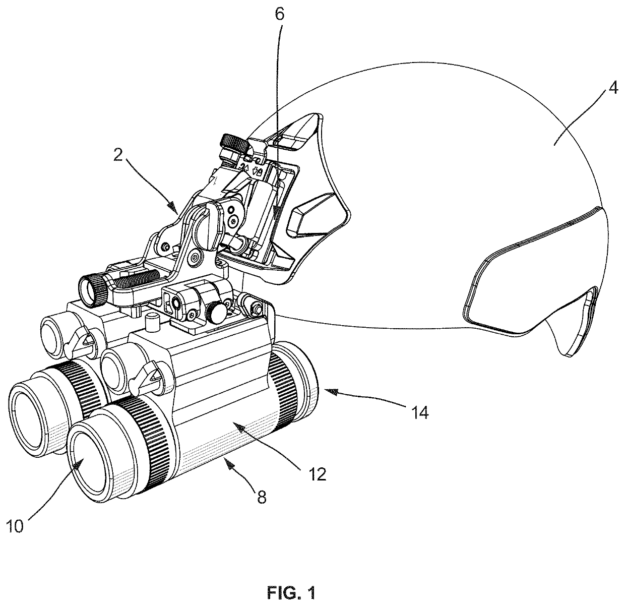
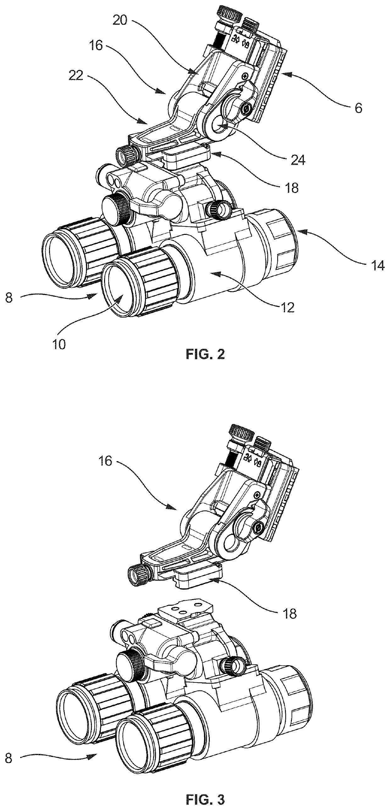
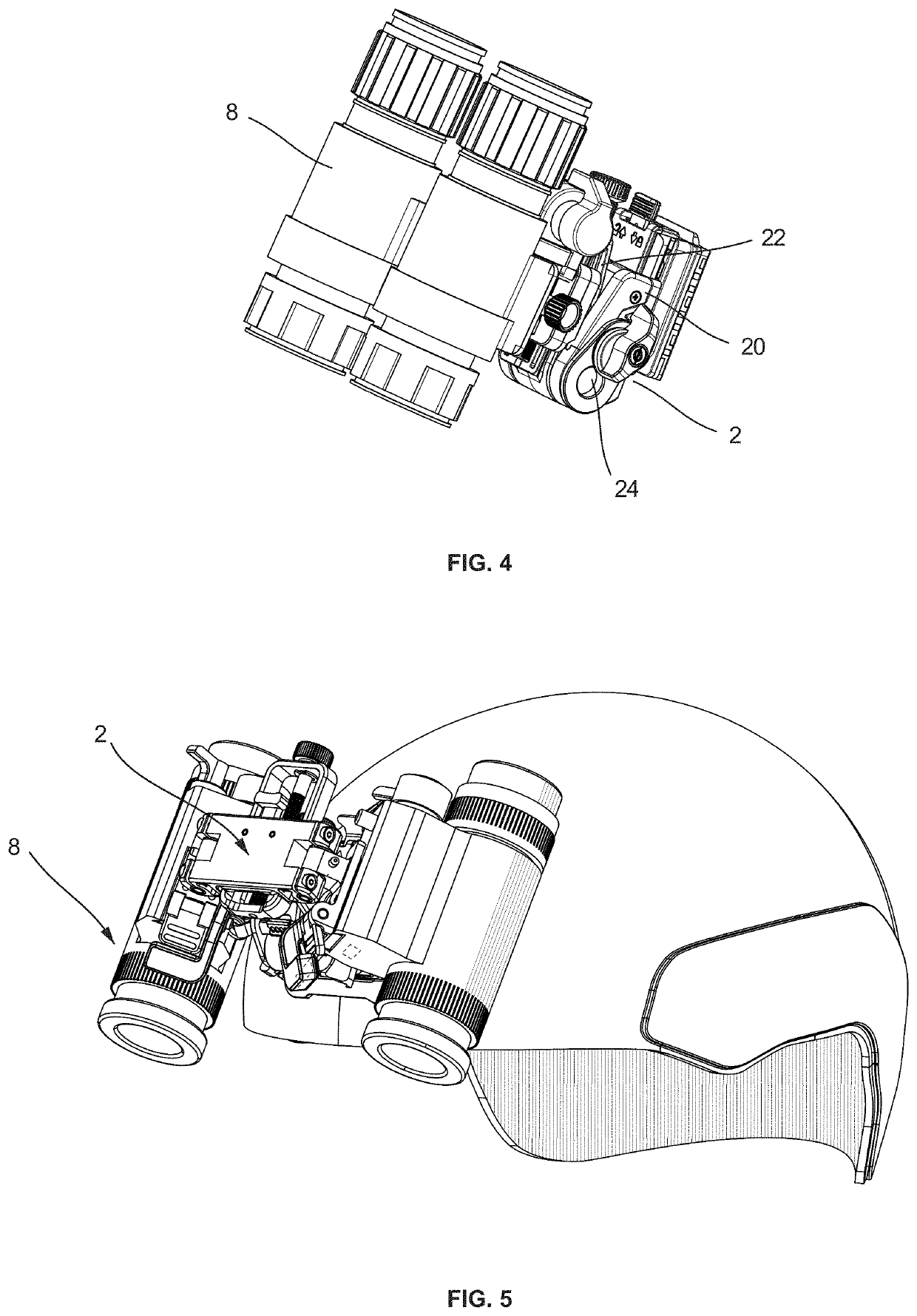
[0062]Referring now to FIGS. 1, 2, 3, 4 and 5, an embodiment of a flip-up helmet mount 2 according to the present invention is shown. The flip-up helmet mount 2 is shown in use with a standard composite helmet with a Visual Augmentation System (VAS) shroud 4. The flip-up helmet mount 2 is attached to the helmet 4 by a helmet block 6. A pair of enhanced night vision goggles (ENVG) 8 are secured to the helmet 4 by use of the flip-up helmet mount 2. Each ENVG 8 shown in FIG. 1 is a device that includes a single objective lens 10, a ENVG housing 12, and an eye-piece 14. The ENVG 8 is attached individually to the helmet mount 2 by a carriage chassis 18, which is mounted to a bracket member 16. The bracket member 16 comprises a bracket member upper 20 and a bracket member lower 22 which can rotate around the bracket member hinge 24. To use the ENVG 8, the operator places it in the position depicted in FIG. 1 and looks into the eye-pieces 14 to see an enhanced image representative of the l...


PUM


Abstract

The present invention relates to a helmet mounting assembly for enhanced night vision goggles, and more particularly to a flip-up helmet mount (2) designed to allow for automatic shutoff of an attached ENVG (8) when stowed, and automatic activation of an ENVG when returned to the in-use position. An automatic shutdown assembly including a magnet module (26) and a magnetically-responsive sensor (36) wherein the magnet module comprising a magnet (28) that emits the necessary magnetic field (34) which influences the magnetically-responsive sensor when in the stowed position in order to turn the ENVG off.

Description

TECHNICAL FIELD[0001]The present invention relates to mounting assemblies for night vision goggles such as enhanced night vision goggles (ENVG), and more particularly to a switch system and mounting system for a single or dual ENVG.BACKGROUND ART[0002]Night vision devices are commonly used by military personnel for conducting operations in low light and night conditions. These night vision devices typically include image intensifier tubes and associated optics that convert infrared and near infrared light into viewable images.[0003]Assemblies for mounting night vision goggles to a helmet or other headpieces are well known in the art. The mounting assemblies allow a user's hands to remain free while viewing a scene through the night vision goggles. Prior art mounting assemblies typically include one or more of the following features: positional adjustment of the night vision goggles between an in-use position and a flip-up stowed position; a quick release system for detachment of ENV...

Claims


Application Information

Patent Timeline
IPC IPC(8): A42B3/04G02B23/12F41H1/04F16C11/04
CPCA42B3/042F16C11/04F41H1/04G02B23/125G02B27/0176G02B2027/0159G02B27/0179
Inventor SCHRODER, WARRENWALL, ALEXANDER
Owner DESIGNWORKS DEFENCE SYST PTY LTD
Learn More