Cable conduit remote control car with rope

A technology of cable duct and remote control car, which is applied in the direction of cable installation, cable installation device, cable laying equipment, etc. It can solve the problems of cable insulation strength reduction, no traction rope conveyor, and difficult cable laying engineering, so as to reduce water leakage , night vision effect is good, the effect of improving the service life

Pending Publication Date: 2020-01-03
PANJIN POWER SUPPLY COMPANY OF STATE GRID LIAONING ELECTRIC POWER SUPPLY +1
View PDF0 Cites 2 Cited by
  • Summary
  • Abstract
  • Description
  • Claims
  • Application Information

AI Technical Summary

Problems solved by technology

[0002] In the process of laying cables in power transmission, substations, and power distribution, underground pipelines need to pull steel wire ropes. The distance between underground pipelines is generally more than 100 meters. There is no better traction rope conveyor, which causes a major problem in cable laying projects.
[0003] The existing technology uses PVC rods to transport the traction rope, which can only be transported about 20 meters. At this distance, the underground pipeline needs to be opened, and then transported again, just like this. After sealing, if the sealing is not good, water and moisture will leak, which will reduce the insulation strength of the cable and reduce the service life. For this reason, we need to develop a special cable duct with a rope remote control car

Method used


Image

  • Cable conduit remote control car with rope
  • Cable conduit remote control car with rope
  • Cable conduit remote control car with rope

Examples


Embodiment Construction

[0028] The following will clearly and completely describe the technical solutions in the embodiments of the present invention with reference to the accompanying drawings in the embodiments of the present invention. Obviously, the described embodiments are only some, not all, embodiments of the present invention. Based on the embodiments of the present invention, all other embodiments obtained by persons of ordinary skill in the art without creative efforts fall within the protection scope of the present invention.

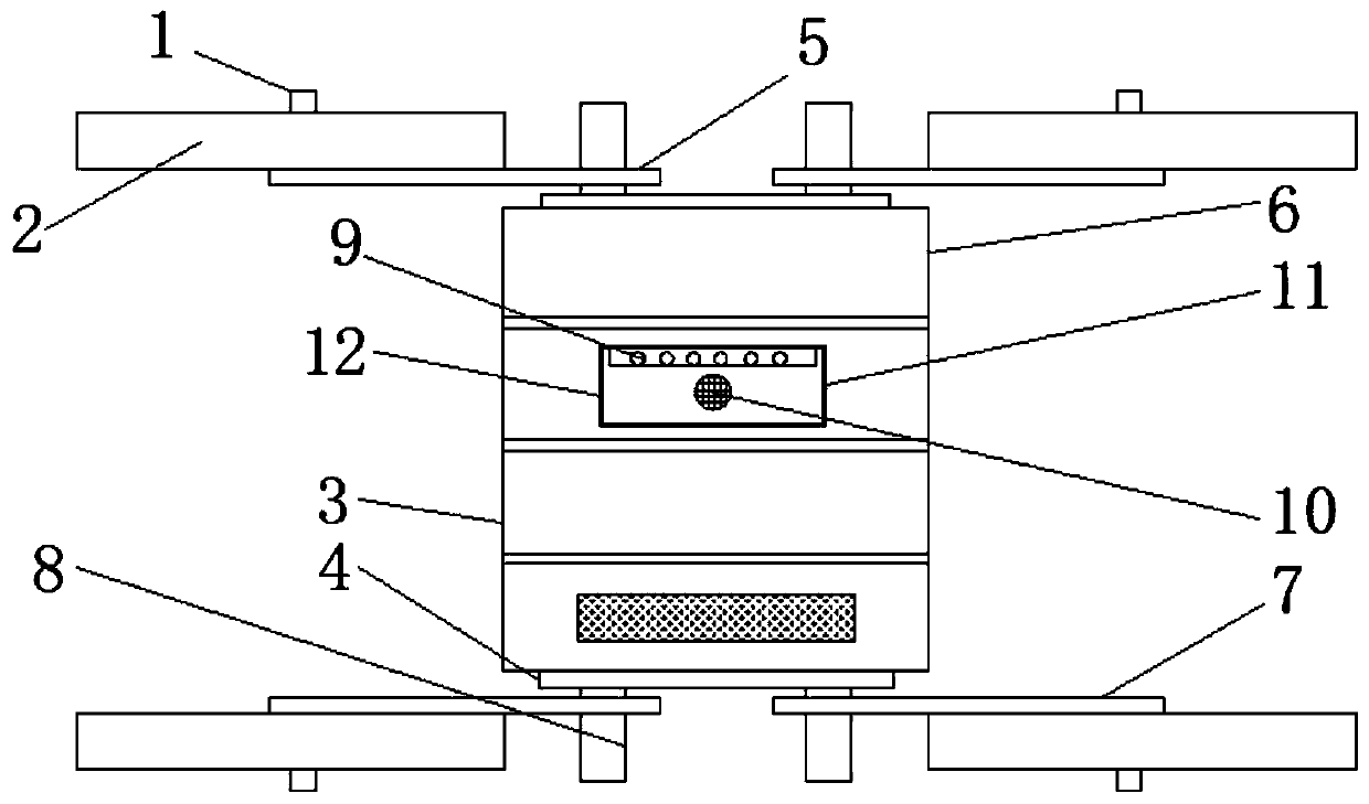
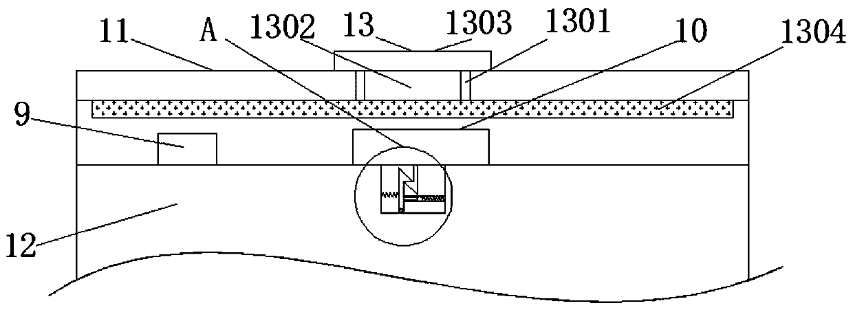
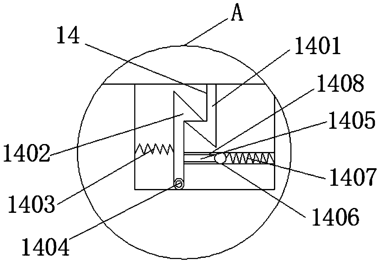
[0029] refer to Figure 1-3 , the remote control car with a cable duct, including the motor pulley shaft 1, the motor pulley 2, the first damping magnetic ring 3, the aluminum alloy baffle 4, the fixed pulley plate 5, the second damping magnetic ring 6, the motor connecting plate 7, Motor shaft 8, lighting unit 9, monitoring unit 10, housing 11, base 12, cleaning mechanism 13, chute 1301, slider 1302, push block 1303, brush rod 1304, clamping mechanism 14, first cl...


PUM


Abstract

The invention discloses a cable conduit remote control car with a rope, which comprises a motor pulley shaft. A motor pulley is connected to the outer side of the motor pulley shaft; a fixed pulley plate is connected to the bottom of the motor pulley; a motor shaft is installed on the inner side of the fixed pulley plate; and an aluminum alloy baffle is connected to the top end of the motor shaft.According to the cable conduit remote control car with the rope, under effects of a clamping mechanism, when the shell is inserted into the inner groove of the base through a first clamping piece connected with the bottom end, a second clamping piece is pressed to rotate leftwards through a movable connecting piece, and meanwhile a first spring is pressed to deform; when the first clamping pieceis clamped with the second clamping piece, the first spring quickly restores the second clamping piece to the original shape, the shell and the base can be conveniently fixed, the shell can conveniently protect a monitoring unit and a lighting unit which are connected to the base, the monitoring unit and the lighting unit are prevented from being damaged by collision of an external force, and a push rod can move leftwards in an open groove in the outer wall of an inner groove of the base by pushing the push rod.

Description

technical field [0001] The invention specifically relates to a remote control car with a cable duct. Background technique [0002] In the process of laying cables in power transmission, substations, and power distribution, underground pipelines need to pull steel wire ropes. The distance between underground pipelines is generally more than 100 meters. There is no better traction rope conveyor, which causes a major problem in cable laying projects. [0003] Existing technology uses PVC rods to transport the traction rope, which can only transport about 20 meters. At this distance, the underground pipeline needs to be opened, and then transported again, just like this. If the plugging is not good, it will leak water and moisture, causing the cable to reduce its insulation strength and reduce its service life. For this reason, we need to develop a special cable duct with a rope remote control car. Contents of the invention [0004] The object of the present invention is to a...

Claims


Application Information

Patent Timeline
Patent Type & Authority Applications(China)
IPC IPC(8): H02G1/08B62D63/02B08B1/00
CPCB08B1/002B62D63/02H02G1/088
Inventor 姜广敏文世喜苑婷张立新宫琳娜索子健金妍郐凤彬王宇吕鹏赵宏郑景红宫兴华王文李天辉侯宇嘉李嵩梁淦张乘宸郭晟城王褚刘树森陈媛谭美玲李冰心金丽李金睿
Owner PANJIN POWER SUPPLY COMPANY OF STATE GRID LIAONING ELECTRIC POWER SUPPLY
Why Eureka
Try Eureka