Imaging adjustment method for television camera

An assembly and adjustment method and TV technology, which are applied to color TV parts, TV system parts, TVs, etc., can solve the problems of indetermination of the optical axis of the TV lens and insufficient clarity of the display screen, and achieve strong practicability and excellent picture quality. clear effect

Active Publication Date: 2013-04-03
LUOYANG INST OF ELECTRO OPTICAL EQUIP OF AVIC
View PDF5 Cites 13 Cited by
  • Summary
  • Abstract
  • Description
  • Claims
  • Application Information

AI Technical Summary

Problems solved by technology

Due to structural limitations, the TV lens does not provide an optical reference, so the optical axis of the TV lens cannot be determined. At present, when the existing TV lens and CCD components are ass

Method used


Image

  • Imaging adjustment method for television camera
  • Imaging adjustment method for television camera
  • Imaging adjustment method for television camera

Examples


Example Embodiment

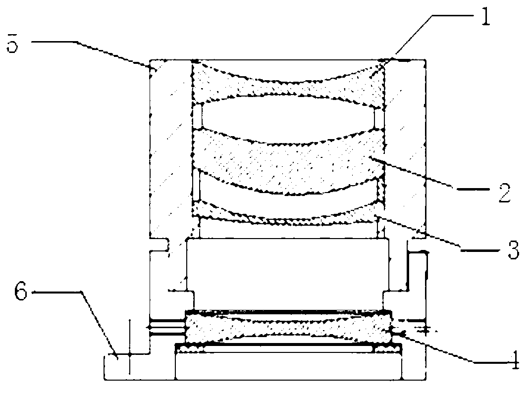
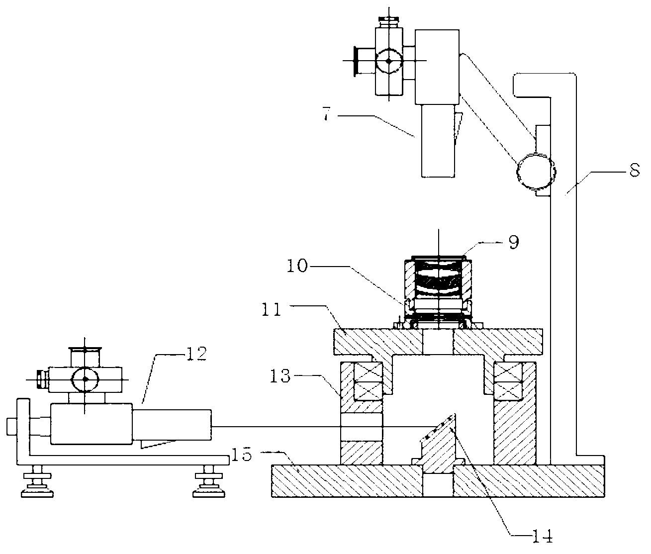
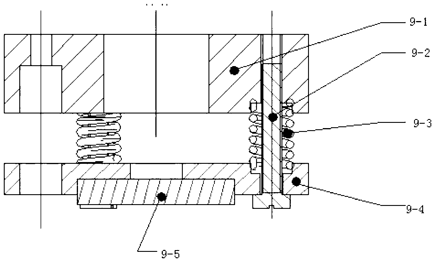
[0023] The specific embodiments of the present invention will be further described below in conjunction with the drawings. figure 1 Among them, the television lens includes a first lens 1, a second lens 2, a third lens 3, a fourth lens 4, a focusing lens barrel 5 and a mounting bracket 6. figure 2 The instruments used in this include: the first inner focusing telescope 7, the second inner focusing telescope 12, the centering device turntable 11, the adjustable reflector 9, and the reflector 14. The centering device turntable 11 is installed on the platform 15 through the support 13 on, image 3 The TV component debugging platform in mainly includes: collimator 16 with identification rate, platform 21 with track and track, power-on equipment 19 and display 20. The specific steps of the imaging installation method of the TV lens are as follows:

[0024] 1. Fix the TV lens 10 to be adjusted to the universal holder of the centering device turntable 11, and adjust the translation scre...


PUM


Abstract

The invention provides an imaging adjustment method for a television camera. The imaging adjustment method includes the steps: fixing the television camera on a turntable of a rotary centering device; erecting a collimator with a cross reticule above the television camera; adjusting the angle of the television camera to fix a crosshair image received by a lower internal focusing telescope; fixing an adjustable reflector above the television camera and adjusting the angle of the reflector to fix a cross reticule image reflected into the collimator by the adjustable reflector; mounting the television camera with the adjustable reflector on a television component debugging platform and adjusting the collimator by taking the normal line of the adjustable reflector as a reference; and removing the adjustable reflector and adjusting the position of a CCD (charge coupled device) by taking the collimator with a discrimination plate as a reference to form the clearest picture. The imaging adjustment method is applicable to all television cameras and high in practicability, a real optical axis of each television camera can be accurately determined, and an accurate optical reference is provided for adjusting television components.

Description

technical field [0001] The invention belongs to optical-mechanical adjustment technology, in particular to an imaging adjustment method of a television lens. Background technique [0002] When the TV assembly is assembled and adjusted, the TV lens and the CCD element are two separate units. Due to structural limitations, the TV lens does not provide an optical reference, so the optical axis of the TV lens cannot be determined. At present, when the existing TV lens and CCD components are assembled and debugged, the center of the CCD cannot be adjusted to the optical axis of the TV lens. Butt the TV lens and CCD according to experience, resulting in the picture of the display is not clear enough. Contents of the invention [0003] The purpose of the present invention is to provide a method for adjusting the image of a TV lens, which can adjust the center of the CCD to the optical axis of the TV lens to make the picture clear. [0004] In order to solve the above-mentioned ...

Claims


Application Information

Patent Timeline
IPC IPC(8): H04N5/225H04N5/64G02B7/00G02B7/182
Inventor 梁雪驰
Owner LUOYANG INST OF ELECTRO OPTICAL EQUIP OF AVIC
Why Eureka
Try Eureka