Fiber optic transducers, fiber optic accelerometers and fiber optic sensing systems

a technology of fiber optic transducer, which is applied in the direction of acceleration measurement using interia force, instruments, optical elements, etc., can solve the problems of limiting the applicability of certain transducer designs, affecting the sensitivity and control of the environment in which the transducer (and other optical elements of the fiber optic sensing system) are used, and requiring sensitivity and control not obtained or available from many conventional transducers

Active Publication Date: 2015-08-04
AVALON SCI
View PDF72 Cites 7 Cited by
  • Summary
  • Abstract
  • Description
  • Claims
  • Application Information

AI Technical Summary

Benefits of technology

[0008]It is to be understood that both the foregoing general description and the following detailed description are exemplary, but are not restrictive, of the invention.

Problems solved by technology

Such transducers suffer from a number of deficiencies.
For example, certain fiber optic sensing applications have spatial restrictions which limit the applicability of certain transducer designs.
Further, the environment in which the transducers (and other optical elements of the fiber optic sensing systems) are used may require sensitivity and control not obtained or available from many conventional transducers.
Further still, the operation of many optical transducers is adversely affected by disturbances along differing axes of motion.

Method used


Image

  • Fiber optic transducers, fiber optic accelerometers and fiber optic sensing systems
  • Fiber optic transducers, fiber optic accelerometers and fiber optic sensing systems
  • Fiber optic transducers, fiber optic accelerometers and fiber optic sensing systems

Examples


Embodiment Construction

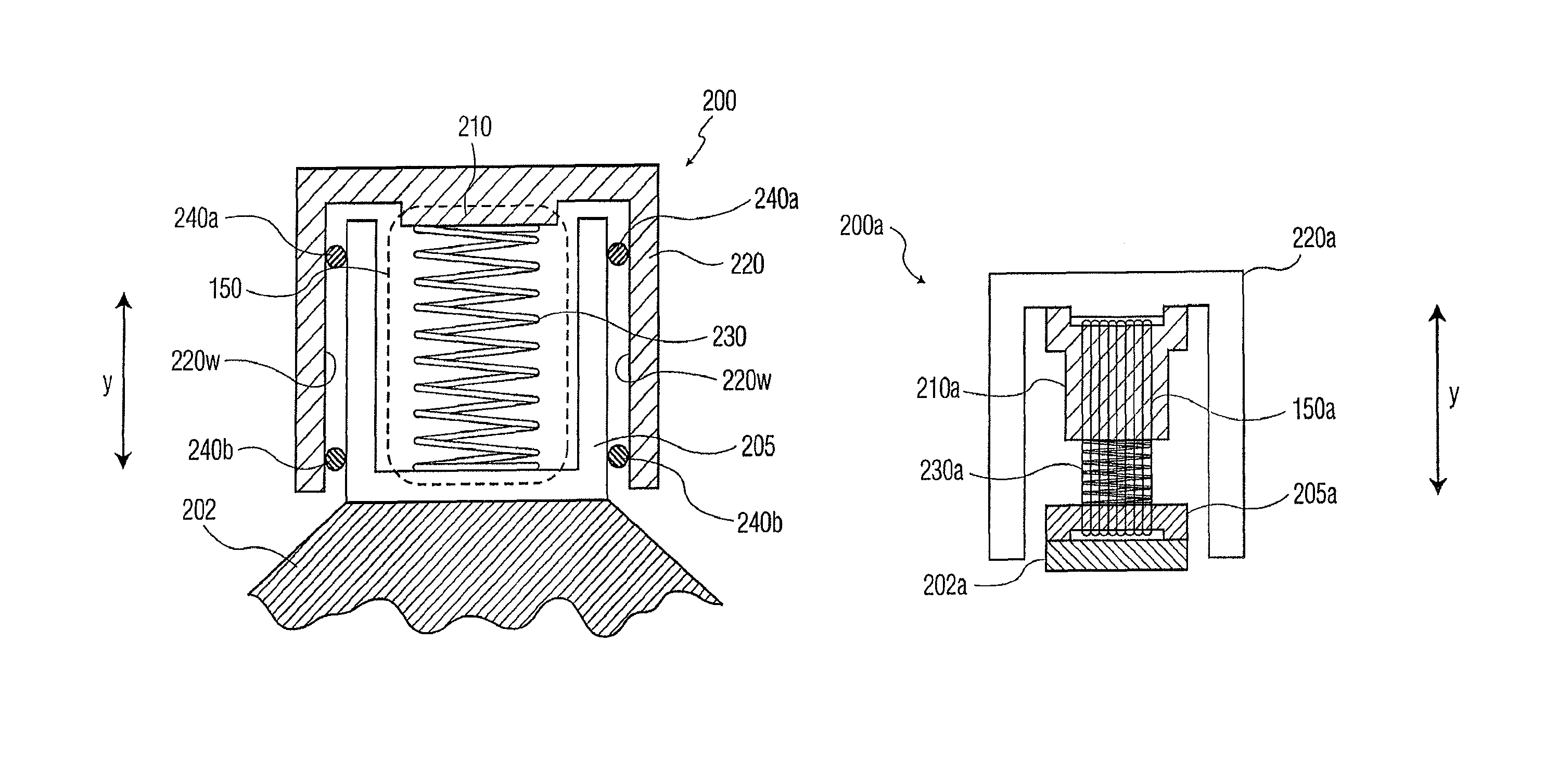
[0022]The invention relates generally to transducers, accelerometers (i.e., interferometers), and fiber optic sensing systems for sensing physical disturbances (e.g., motion, acceleration, perturbations, etc.) of a body of interest. As will be appreciated by those skilled in the art, a fiber optic accelerometer (sometimes referred to as a fiber optic sensor or a fiber optic interferometer) is an element of a system for measuring physical motion of a body of interest using fiber optic technology. The accelerometer includes a transducer that converts a physical disturbance of the body of interest into a change in strain applied to a length of optical fiber of the transducer.

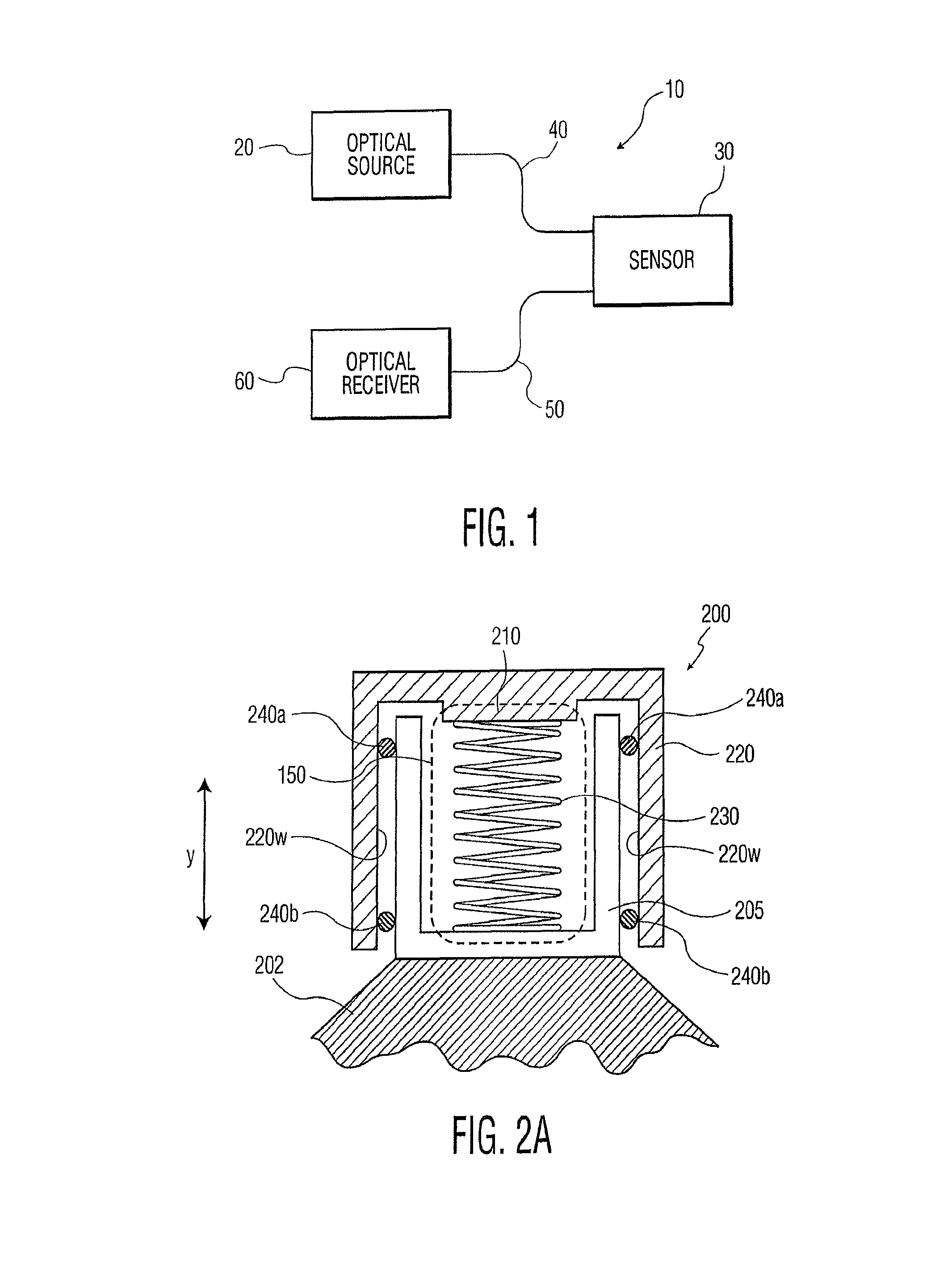
[0023]Referring to FIG. 1, fiber optic accelerometer 10 includes optical source 20 (e.g., an LED, an SLED, a laser, etc.), sensor 30 (e.g., an interferometer), optical receiver 60 (e.g., an optical detector such as a photodetector), optical fiber 40 for transmitting light from optical source 20 to sensor 30, and op...


PUM


Abstract

A fiber optic transducer is provided. The fiber optic transducer includes a fixed portion configured to be secured to a body of interest, a moveable portion having a range of motion with respect to the fixed portion, a spring positioned between the fixed portion and the moveable portion, and a length of fiber wound between the fixed portion and the moveable portion. The length of fiber spans the spring. The fiber optic transducer also includes a mass engaged with the moveable portion. In one disclosed aspect of the transducer, the mass envelopes the moveable portion.

Description

RELATED APPLICATION[0001]This application claims the benefit of priority to U.S. Provisional Patent Application Ser. No. 61 / 279,607, filed on Oct. 23, 2009, the contents of which are incorporated in this application by reference.TECHNICAL FIELD[0002]This invention relates generally to the field of fiber optic sensing systems, and more particularly, to improved fiber optic transducers, accelerometers, interferometers, and improved fiber optic sensing systems.BACKGROUND OF THE INVENTION[0003]Fiber optic sensing systems are widely used for sensing disturbances (e.g., motion, acceleration, sound, etc.). Such fiber optic sensing systems often include a transducer for converting the disturbance into a phase change of light in an optical fiber.[0004]Such transducers suffer from a number of deficiencies. For example, certain fiber optic sensing applications have spatial restrictions which limit the applicability of certain transducer designs. Further, the environment in which the transducer...

Claims


Application Information

Patent Timeline
Patent Type & Authority Patents(United States)
IPC IPC(8): G01B9/02G01H9/00G01P15/093G01V1/18G01D5/353
CPCG01B9/02014G01B9/0201G01B9/02027G01D5/35312G01D5/35377G01H9/004G01P15/093G01V1/181G01D5/35354G01B9/0205G01D5/35316G01L1/246G02B6/022G01B9/02G01D5/26G01D5/353G01D5/35306G01P15/00G01P15/02G01V1/18G01B9/02015
Inventor ANDERSEN, JAMES KENGOGOLDNER, ERIC LEECHERBETTCHIAN, AGOP HYGASOVBAKER, GERALD ROBERTBEATSON, DAVID T.
Owner AVALON SCI
Why Eureka
Try Eureka