Stacker crane

a technology of stacker crane and crane body, which is applied in the direction of transportation and packaging, lifting devices, storage devices, etc., can solve the problems of complicated platform guiding system, difficult to lower the cost of the lower frame itself, and high cost of the connecting frame, so as to reduce the cost of manufacturing the lower frame. , the effect of simple structur

Active Publication Date: 2015-08-11
DAIFUKU CO LTD
View PDF7 Cites 0 Cited by
  • Summary
  • Abstract
  • Description
  • Claims
  • Application Information

AI Technical Summary

Benefits of technology

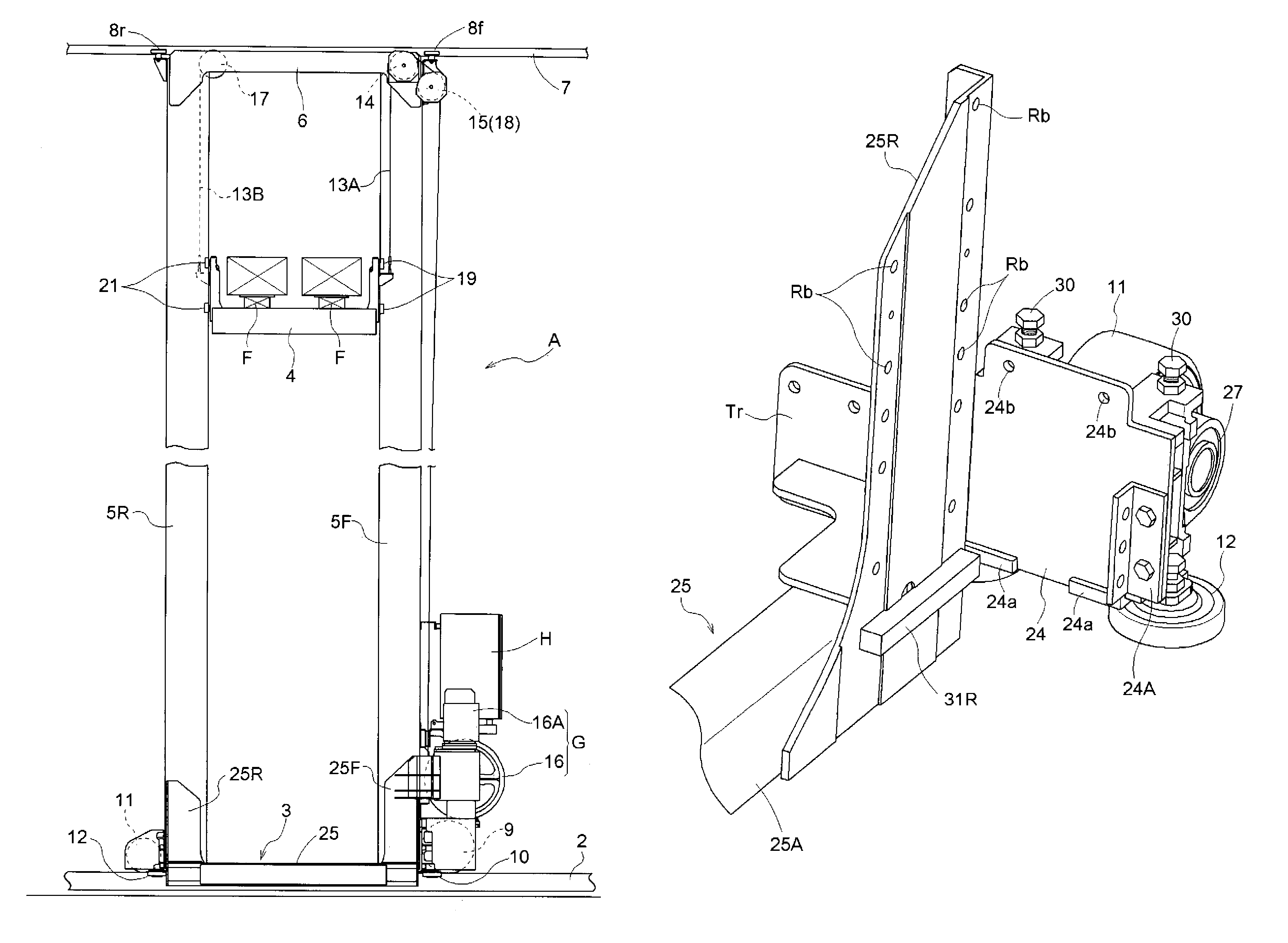
[0018]That is to say, according to the invention, the lower end surface of the front support rod is held on the flange of the front wheel support frame, while the lower end surface of the rear support rod is held on the flange of the rear wheel support frame. Therefore, the weight of the front and rear support rods, the upper frame, the platform and the articles to be held by the platform is born by the front and rear wheel support frames, so that heavy weight acting on the connecting frame, which connects the front and rear running wheels support frames for supporting the running wheels, can be prevented.
[0056]In short, according to the sixth characteristic structure of the present invention, a stacker crane can be provided by which the posture of the front and rear support rods can be controlled, in addition to the function and effect in accordance with anyone of the first to fifth characteristic structures. According to the structure, the inclination of the front and rear support rods in the back and forth direction can be prevented, without making the construction of the lower frame overly complex.

Problems solved by technology

Since such a heavy weight acts on the connecting frame, the connecting frame must have sufficient strength for the weight, which made the connecting frame expensive and difficult to lower cost for the lower frame itself.
This stacker crane is constructed such that the platform is guided by the extended guide rails, which complicates the guiding system of the platform.
Therefore, the lower frame of this conventional type of stacker crane cannot be made cheaper.

Method used


Image

  • Stacker crane
  • Stacker crane
  • Stacker crane

Examples


Embodiment Construction

[0074]As required, detailed embodiments of the present invention are disclosed herein; however, it is to be understood that the disclosed embodiments are merely exemplary of the invention, which can be embodied in various forms. Therefore, specific structural and functional details disclosed herein are not to be interpreted as limiting, but merely as a basis for the claims and as a representative basis for teaching one skilled in the art to variously employ the present invention in virtually any appropriately detailed structure. Further, the terms and phrases used herein are not intended to be limiting; but rather, to provide an understandable description of the invention. While the specification concludes with claims defining the features of the invention that are regarded as novel, it is believed that the invention will be better understood from a consideration of the following description in conjunction with the drawing figures, in which like reference numerals are carried forwar...


PUM


Abstract

A stacker crane includes a lower frame having running wheels running along a rail at both front and rear end portions thereof. The lower frame has a connecting frame that connects front and rear wheel support frames for supporting the running wheels to each other. The front support rod is held by a flange at its lower end surface, which is formed at the lower end portion of the front side wheel support frame. The side surface of the front support rod is connected and supported by the front side wheel support frame. The rear support rod is held by a flange, which is formed at the lower end portion of the rear side wheel support frame at its lower end surface and the side surface of the rear support rod is connected and supported by the rear side wheel support frame 24.

Description

CROSS-REFERENCE TO RELATED APPLICATIONS[0001]This application claims the priority, under 35 U.S.C. §§119 and 371, of Japanese patent application No. 2010-280641, filed Dec. 16, 2010; the prior application is herewith incorporated by reference in its entirety.STATEMENT REGARDING FEDERALLY SPONSORED RESEARCH OR DEVELOPMENT[0002]Not ApplicableFIELD OF THE INVENTION[0003]The present invention relates to a stacker crane. In particular, a stacker crane including a lower frame having running wheels runnable along rails at both front and rear end portions of the frame, front and rear support rods standing from the front and rear end portions of the lower frame, an upper frame for connecting the top ends of the front and rear support rods to each other, and a platform being guided by the front and rear support rods.[0004]Such a stacker crane is installed in a storage so that it travels along the front side of storage racks having storage areas for storing articles lengthwise and breadthwise,...

Claims


Application Information

Patent Timeline
Patent Type & Authority Patents(United States)
IPC IPC(8): B65G1/06B66F9/07B66B9/16B65G1/04
CPCB66F9/072B65G1/0407
Inventor IWATA, MASASHIGE
Owner DAIFUKU CO LTD
Why Eureka
Try Eureka