Electro-optic effect based optical voltage transformer

a voltage transformer and optical effect technology, applied in the field of electrical power equipment, can solve the problems of insufficient safety and reliability, difficult to overcome many limitations of traditional electromagnetic inductive or capacitive voltage divider transformers, and the overwhelming majority of limitations of laboratory phase, etc., to achieve uniform electric field distribution, good electrical shielding, and good conductivity

Active Publication Date: 2013-03-28
BEIJING AEROSPACE TIMES OPTICAL ELECTRONICS TECH
View PDF5 Cites 22 Cited by
  • Summary
  • Abstract
  • Description
  • Claims
  • Application Information

AI Technical Summary

Benefits of technology

[0005]The technical problem solved in this invention is: in order to overcome the shortcomings of the existing technology, an electro-optic effect based optical voltage transformer is provided, so that the light source center wavelength drift is effectively controlled, the optical power fluctuations caused by factors such as the optical fiber vibration are eliminated, and the stability and reliability of the optical system and the accuracy of the data are improved.
[0006]The second technical problem solved in this invention is: in order to solve the problems of the existing optical voltage transformer such as large size, heavy weight, high cost, etc., an optical voltage transformer integrated in GIS cavity is provided which has small size, light weight, good shielding effect and flexible application.
[0007]The third technical problem solved in this invention is: a tank-type single-phase optical voltage transformer is provided which has small size, light weight, good shielding effect and flexible application.

Problems solved by technology

With the continuous improvement of the power system voltage levels, the traditional electromagnetic inductive or capacitive voltage divider transformer is difficult to overcome many limitations due to its restrictions of sensing mechanism.
In China, some universities such as Tsinghua University, Huazhong University of Science and Technology, etc and many enterprises such as 26th Institute of China Electronics Technology Group Corporation, China Electric Power Research Institute, Shanghai Transformer Factory, etc have engaged in this research successively since 1992, and now many types of optical voltage transformer prototype have been developed but the overwhelming majority of them are limited to laboratory phase.
Currently, most of the existing optical voltage transformers have the problems of variation with temperature of the light source light-emitting wavelength and instability of output power; the existing optical voltage transformers also have the problems of large size, heavy weight, high cost, the phenomenon of partial discharge and withstanding voltage, and the additional insulation design is required, therefore the hidden dangers due to pressure, humidity and other factors are increased, and the long-term safety and reliability can not be ensured well; in the bonding process, the multiple discrete optical components will inevitably produce micro outward movement during the curing process, which affecting the accuracy of azimuth; and the follow-up electronic circuits will directly bring error to the optical signal due to the drift caused by temperature changes, which reduces the stability of the system; in addition, as far as modulation scheme is concerned, compared with horizontal modulation, longitudinal modulation optical voltage transformers also have the problems of high cost of insulation under high pressure, out of proportion between the output signal and the electric field and difficult signal demodulation.

Method used


Image

  • Electro-optic effect based optical voltage transformer
  • Electro-optic effect based optical voltage transformer
  • Electro-optic effect based optical voltage transformer

Examples


Embodiment Construction

[0056]In order to make the technical problems solved by this invention, the technical solutions and the beneficial effect more clearly and easy to understand, further detailed description of this invention will be made combined with drawings and embodiments. It should be understood that the detailed embodiments described here are only used to explain this invention but not to limit this invention.

[0057]The optical voltage transformer described in this invention uses Pockels effect to accurately measure voltage or electric field.

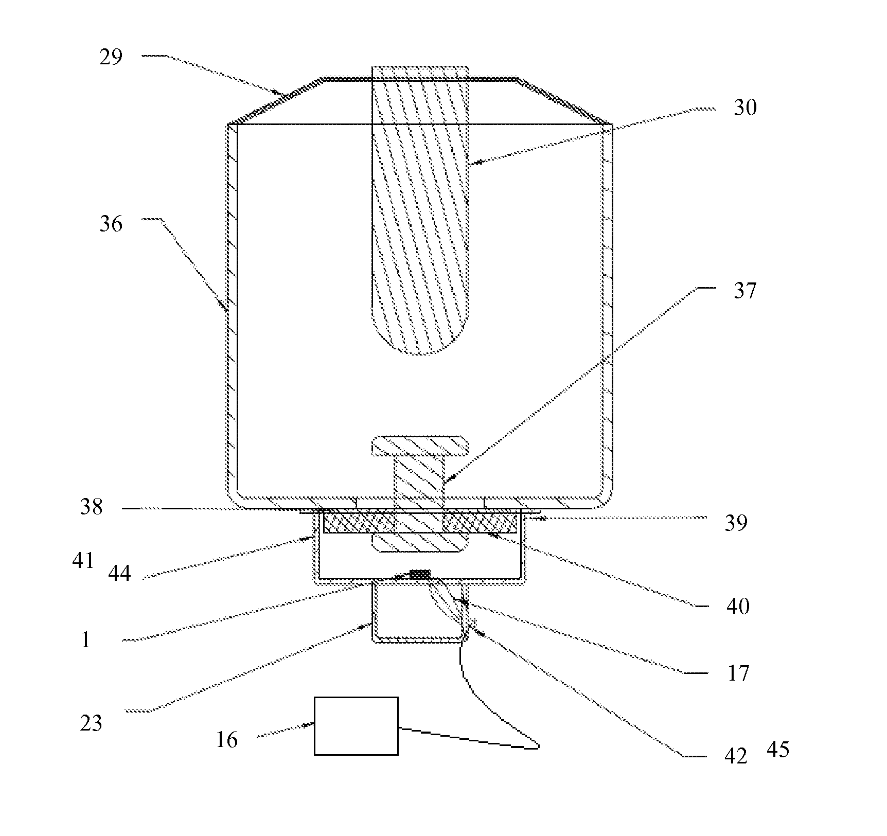
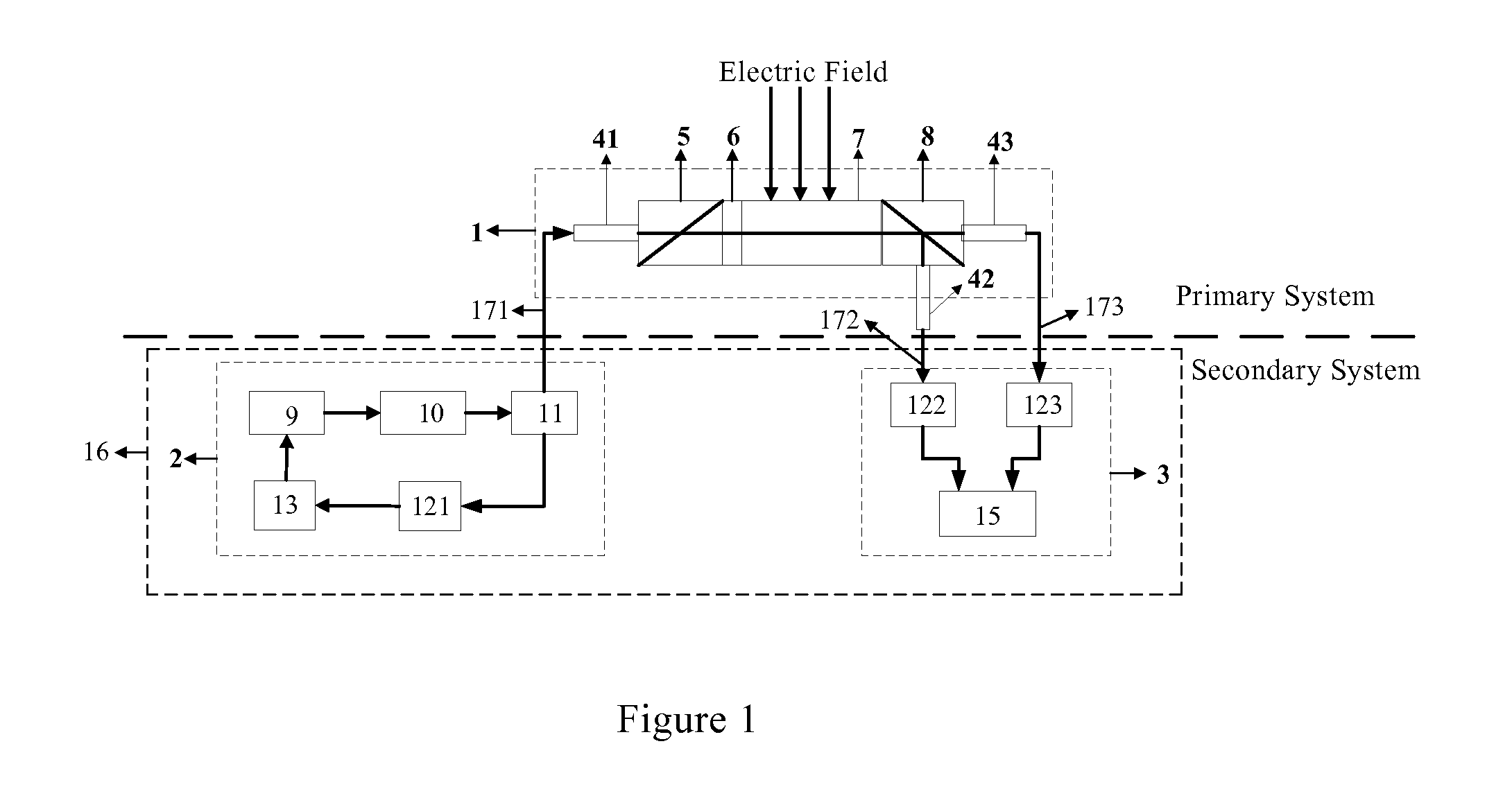
[0058]FIG. 1 shows the schematic structure of the electro-optic effect based optical voltage transformer of this invention, which includes an optical voltage sensor head 1 and an electrical unit 16, the electrical unit 16 includes an optical closed-loop feedback control unit 2 and a signal processing unit 3, the electrical unit 16 is connected to an external back-end host computer or a combination unit.

[0059]The optical voltage sensor head 1 is in the primary...


PUM


Abstract

An electro-optic effect based optical voltage transformer comprises an optical voltage sensor head and an electrical unit, wherein the electrical unit comprises an optical closed-loop feedback control unit and a signal processing unit, the optical closed-loop feedback control unit is connected to the optical voltage sensor head and the optical voltage sensor head is connected to the signal processing unit. In this invention, the light source output power is more stable, the light source center wavelength drift is effectively controlled and the output power coastdown caused by light source aging is prevented; the optical power fluctuation of the optical polarization caused by factors such as temperature, optical fiber vibration, etc., is eliminated, which is conductive to stability and reliability of the optical system; the accuracy of data is improved.

Description

FIELD OF THE INVENTION[0001]This invention relates to electrical power equipment technical field, especially to an electro-optic effect based optical voltage transformer.BACKGROUND OF THE INVENTION[0002]High-voltage power transformer is the most basic measurement equipment which provides measurement, control and relay protection for the power system. With the continuous improvement of the power system voltage levels, the traditional electromagnetic inductive or capacitive voltage divider transformer is difficult to overcome many limitations due to its restrictions of sensing mechanism. Optical voltage transformer is a novel transformer which performs voltage measurement using photonics technology and optical fiber sensing technology. Compared with the traditional transformers, in the optical voltage transformer high voltage signal is transmitted to the secondary equipment via optical fiber, so that insulation is greatly simplified, bandwidth is high, dynamic range is wide and it is ...

Claims


Application Information

Patent Timeline
Patent Type & Authority Applications(United States)
IPC IPC(8): G01R19/155
CPCG01R19/155G01R15/247G01R15/242
Inventor WANG, WEIZHANG, ZHIXINTAN, JINQUANWANG, XUEFENGXIA, JUNLEI
Owner BEIJING AEROSPACE TIMES OPTICAL ELECTRONICS TECH
Why Eureka
Try Eureka