Method for forming a geothermal well

a geothermal well and well-forming technology, applied in the direction of directional drilling, lighting and heating apparatus, borehole/well accessories, etc., can solve the problem of significant efficiency loss of the system, and achieve the effect of high thermal conductivity

Inactive Publication Date: 2015-08-18
MECHANICAL & ELECTRICAL CONCEPTS
View PDF6 Cites 37 Cited by
  • Summary
  • Abstract
  • Description
  • Claims
  • Application Information

AI Technical Summary

Problems solved by technology

However, as the supply and return pipes are disposed in the same wellbore and separated by only a few inches, an undesirable transfer of heat occurs between the supply and return pipes, thus resulting in a significant efficiency loss to the system.

Method used


Image

  • Method for forming a geothermal well
  • Method for forming a geothermal well
  • Method for forming a geothermal well

Examples


Embodiment Construction

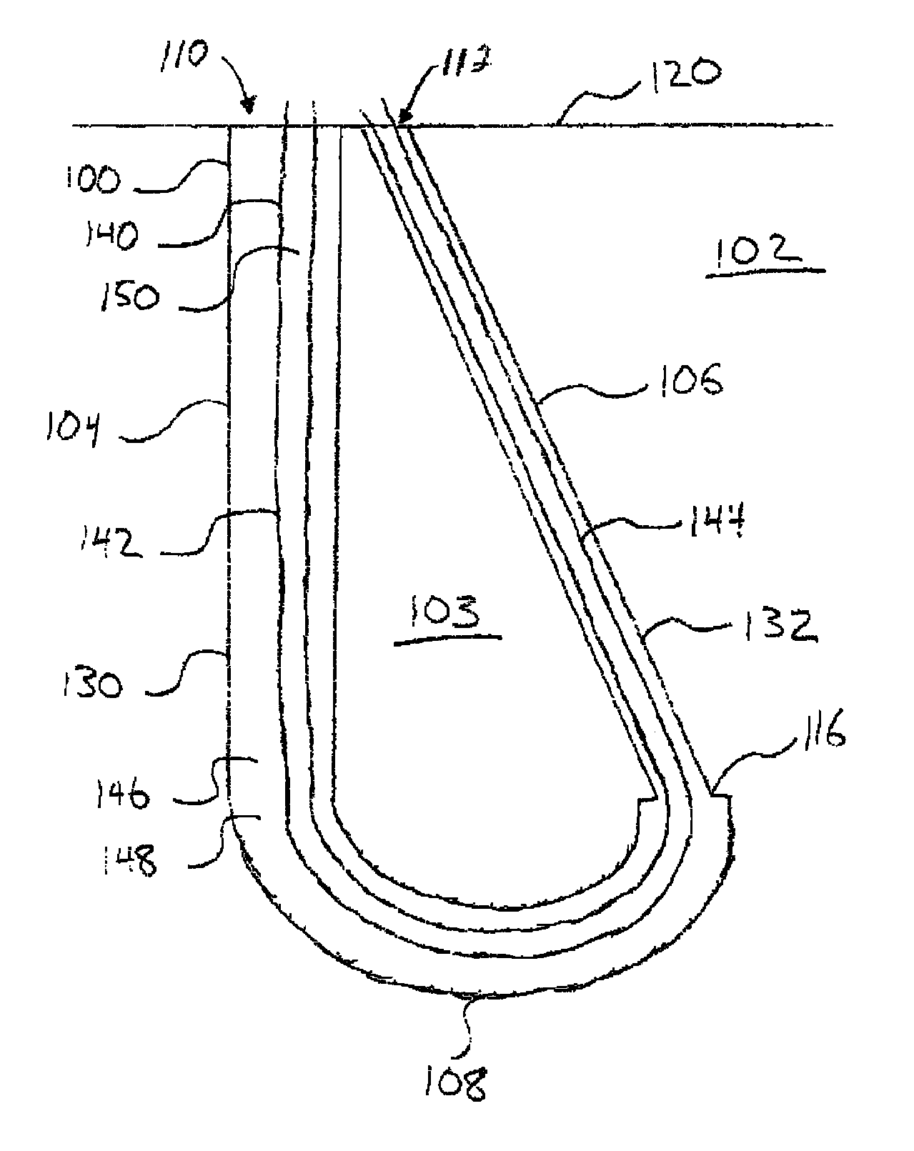
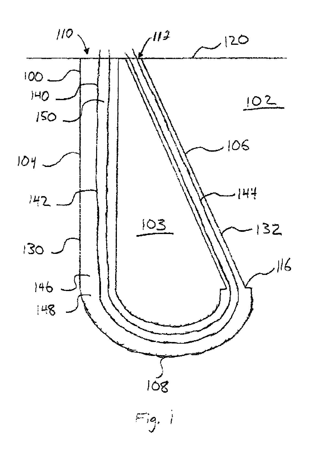
[0020]FIG. 1 depicts a cross-sectional view of an illustrative wellbore loop 100, according to one or more embodiments. The wellbore loop 100 can be disposed in a subsurface environment 102 and can be used in geothermal well applications, such as geothermal cooling or heating applications. For example, a fluid medium 150 can flow through a tube 140 disposed in the wellbore loop 100, and geothermal heat transfer can take place between the fluid medium 150 and the surrounding subsurface environment 102. The fluid medium 150 can be a liquid, gas, or two a two phase mixture. The subsurface environment 102 can include, but is not limited to, dirt, sand, clay, silt, and rock.

[0021]The wellbore loop 100 can have a first segment 104 and a second segment 106 coupled together with an arcuate bottom segment 108. As shown, the first segment 104 can be substantially vertical and the second segment 106 can be angled with respect to vertical; however, either segment 104, 106 can be vertical, subst...


PUM


Abstract

Methods for forming a geothermal well are provided. A method for forming a geothermal well can include drilling a first wellbore having a substantially linear segment connected to an arcuate segment. A second wellbore can be drilled to connect to a terminating end of the arcuate segment, thereby forming a wellbore loop. A thermally conductive tube can be disposed through the wellbore loop.

Description

CROSS-REFERENCE TO RELATED APPLICATION[0001]This application claims priority to U.S. Provisional Patent Application having Ser. No. 61 / 553,019, filed Oct. 28, 2011, which is incorporated by reference herein.BACKGROUND[0002]1. Field[0003]Embodiments described generally relate to methods for forming a geothermal well. More particularly, such embodiments relate to methods for drilling a geothermal wellbore loop and flowing a fluid medium through the wellbore loop to exchange heat with a subsurface environment.[0004]2. Description of the Related Art[0005]A geothermal wellbore generally encases vertical supply and return pipes that are parallel to one another and connected with a U-shaped bend at the bottom. A fluid medium flows down the supply pipe and back up the return pipe exchanging heat with the surrounding subsurface environment throughout the flow path. However, as the supply and return pipes are disposed in the same wellbore and separated by only a few inches, an undesirable tra...

Claims


Application Information

Patent Timeline
Patent Type & Authority Patents(United States)
IPC IPC(8): E21B7/04E21B7/06E21B43/30E21B7/00F24J3/08
CPCE21B7/00E21B7/067E21B43/30F24J3/083E21B7/04F24J3/081F24J2003/088Y02E10/12Y02E10/125F24T10/15F24T2010/53Y02E10/10
Inventor HARRIS, WILLARD D.BATTEN, MICHAEL
Owner MECHANICAL & ELECTRICAL CONCEPTS
Why Eureka
Try Eureka