
Modular control apparatus

a control apparatus and module technology, applied in electrical apparatus, electrical circuits, coupling device connections, etc., can solve problems such as contact-making errors, avoid contact-making errors, avoid potential short circuits, and increase miniaturization

Active Publication Date: 2015-08-18
PILZ (COMPANY)
View PDF30 Cites 23 Cited by
  • Summary
  • Abstract
  • Description
  • Claims
  • Application Information

AI Technical Summary

Benefits of technology

[0008]Against this background, it is an object of the present invention to provide a control apparatus of the type mentioned at the outset which avoids contact-making errors or faulty contacts, and therefore avoids potential short circuits, in the case of increasing miniaturization or a relatively small design.
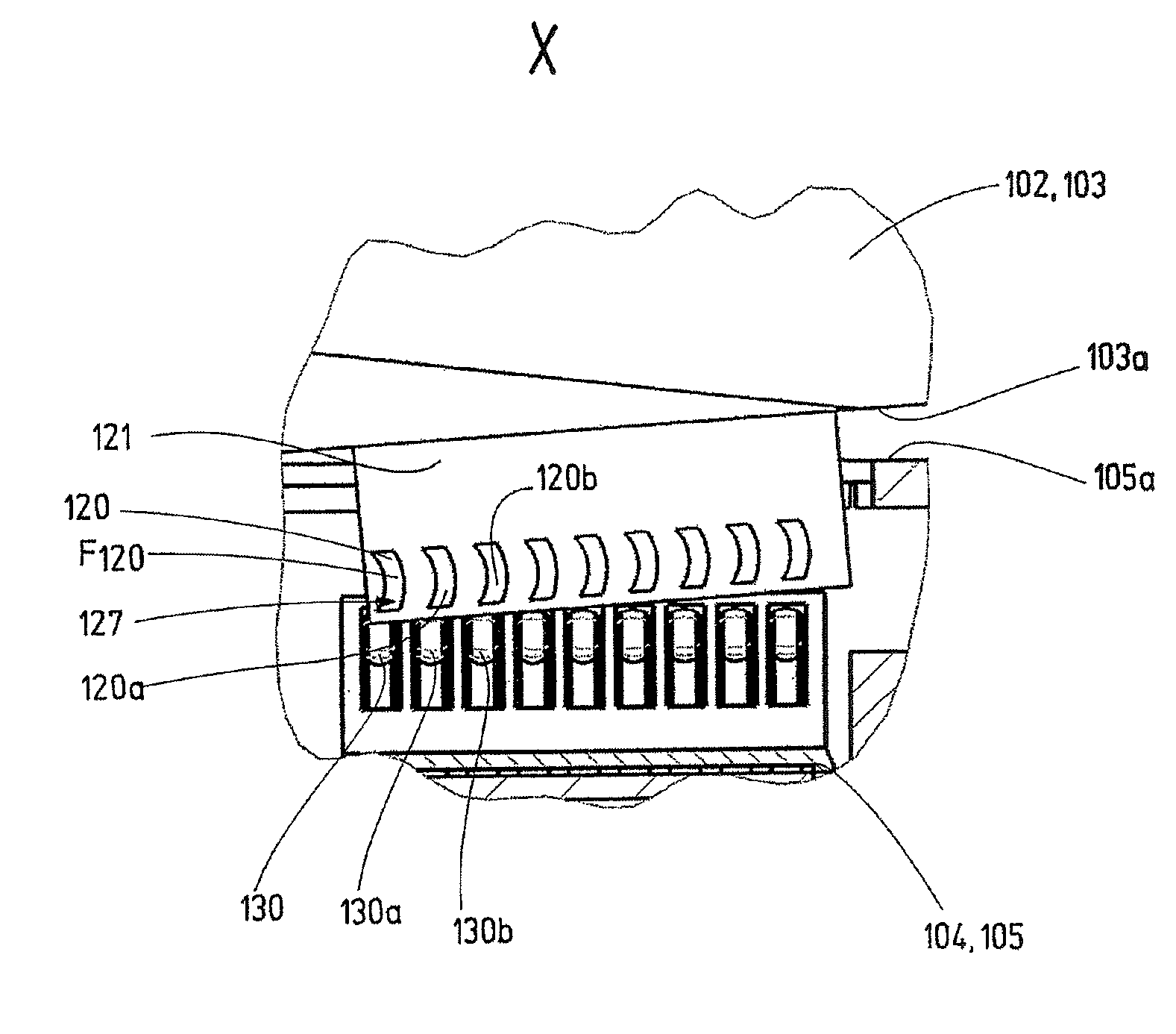
[0012]An undesired contact is produced in particular when a first contact in the course of the pivoting movement makes contact with a second mating contact, which is assigned to a second contact next to the first contact (in the radial direction, starting from the pivot point) (and is not assigned to the first contact). The contacts and / or the mating contacts are in this case arranged next to one another, in particular in a contact plane which runs perpendicular to the pivot axis. It has been found that such undesired contact-making is dependent on the radial distance between the respective (first) contact and the pivot point and dependent on the relative distance between the contacts. Owing to the fact that the leading end of the contact area of the respective (first) contact comprises at least one section which is inclined towards the pivot axis plane (plane which is arranged perpendicular to the boundary plane and is defined by the pivot axis), the situation is avoided in which the contact area, in the course of the pivoting movement, makes contact with the (second) mating contact, which is assigned to the (second) contact next to the respective (first) contact. The outer contour of the exposed contact area is matched to the pivoting movement. An exposed contact area should in particular be understood to mean the outwardly exposed or electrically conductive area with which contact can be made. In the case of a small design, in particular a small distance between the contacts or contact areas and / or a small radial distance from the pivot point, contact-making errors or undesired contacts, and therefore possibly short circuits, can therefore be prevented. Very precise contact-making is now possible.
[0013]Overall, the novel control apparatus and the novel module or module part therefore make it possible to avoid contact-making errors or faulty contacts, and therefore possibly short circuits, in the case of a small design. The abovementioned object is therefore completely achieved.
[0019]In this refinement, said outer contour can be assumed to be a conventional rectangular outer contour which is matched in such a way that it comprises the inclined section. The implementation of the inclined section is therefore simple.
[0023]In this refinement, optimum matching with respect to the likewise curved movement path of the pivoting movement is possible.
[0035]This refinement ensures that a fixedly defined (clean) pivoting movement about a fixedly defined pivot point takes place. The risk of undesired contact-making is therefore even further reduced.

Problems solved by technology

A problem with such control apparatuses comprising pivotable module parts may be that, in the case of a relatively small design, contact-making errors can occur when the module parts are combined by a pivoting movement.

Method used


Image

  • Modular control apparatus
  • Modular control apparatus
  • Modular control apparatus

Examples


Embodiment Construction

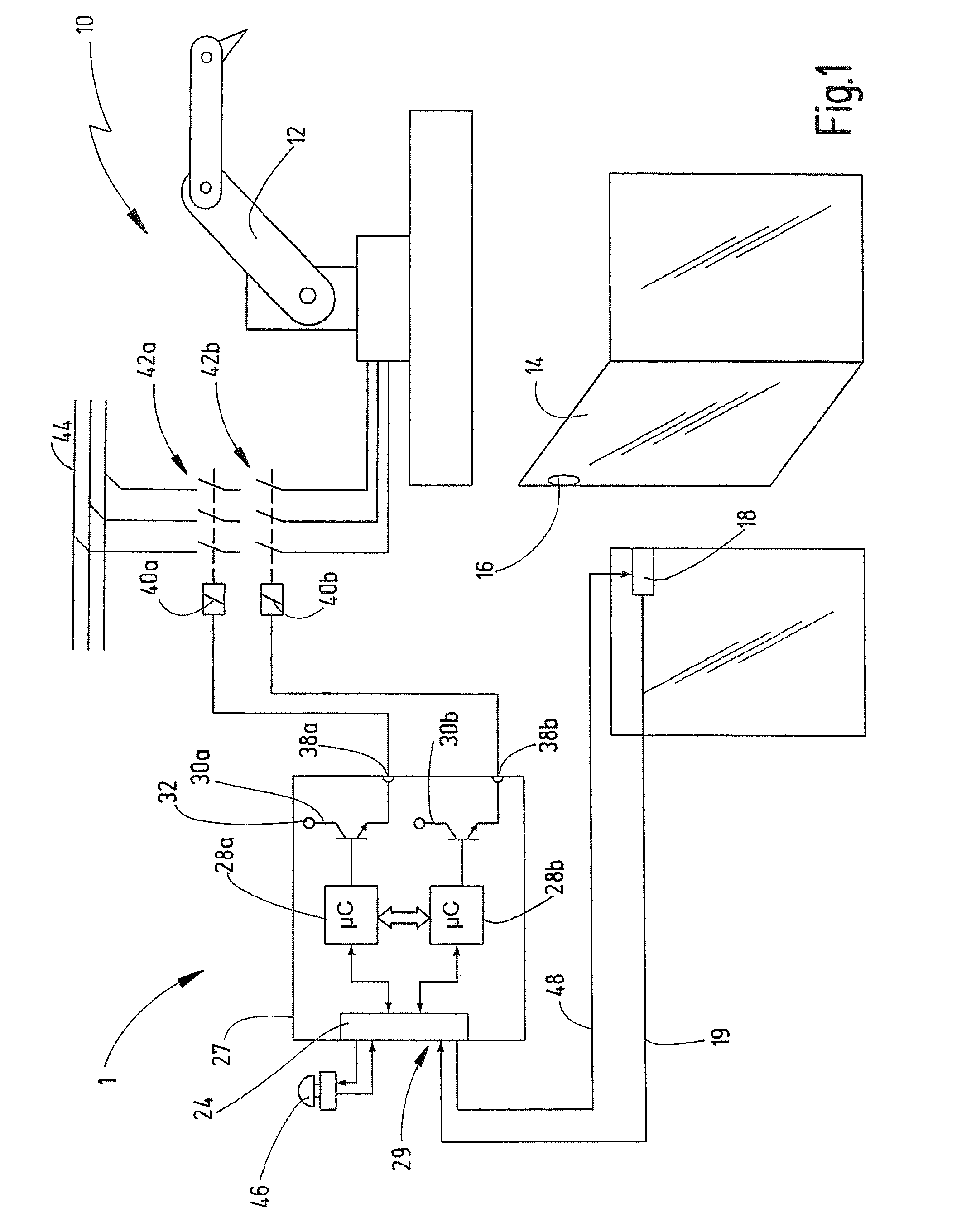
[0062]FIG. 1 illustrates a technical installation 10 with an exemplary embodiment of the novel control apparatus 1 for the automated control of the technical installation 10. In this exemplary embodiment, the control apparatus 1 is configured for the failsafe shutdown of the installation 10, i.e. the control apparatus 1 is used for safety tasks. The installation 10 in this case comprises, by way of example, a robot 12, whose movements during working operation pose a risk to people in the working area of the robot 12. For this reason, the working area of the robot 12 is safeguarded by a safety fence with a safety door 14. The safety door 14 enables access into the working area of the robot 12, for example for maintenance work or for setup work. During normal working operation, however, the robot 12 should only be able to operate when the safety door 14 is closed. As soon as the safety door 14 is opened, the robot 12 needs to be shut down or brought into a safe state in another way.

[0...


PUM


Abstract

A control apparatus has a module having first and second module parts, which can be mechanically and electrically combined to form a combined arrangement. The first and second module parts each comprise a housing having a boundary surface opposite one another in the combined arrangement that define a boundary plane. The first and second module parts are combined by a pivoting movement about a pivot axis arranged perpendicular to the boundary plane. One of the module parts has a number of contacts comprising a first electrical contact, and the other module part has a number of mating contacts comprising a first electrical mating contact. In the combined arrangement, each electrical contact makes contact with its corresponding mating contact for electrical connection between the first and second module parts. The contacts comprise conductor tracks on a nonconductive board such that a printed circuit board is formed.

Description

CROSS-REFERENCES TO RELATED APPLICATIONS[0001]This application is a continuation of international patent application PCT / EP2012 / 064683 filed on Jul. 26, 2012 designating the U.S., which international patent application has been published in German language and claims priority from German patent application DE 10 2011 110 184.9 filed on Aug. 9, 2011. The entire contents of these priority applications are incorporated herein by reference.BACKGROUND OF THE INVENTION[0002]The present invention relates to a modular control apparatus for the automated control of a technical installation.[0003]A control apparatus in terms of the present invention can be, for example, a modular control apparatus for a configurable or programmable controller. It may be a configurable controller such as, for example, that which is marketed by the applicant of the present invention under the trade name PNOZ® or a programmable controller such as, for example, that which is marketed by the applicant under the tr...

Claims


Application Information

Patent Timeline
Patent Type & Authority Patents(United States)
IPC IPC(8): H01R13/629H01R9/26H01R12/72H05K7/14H01R12/70
CPCH01R12/721H01R9/2675H01R12/7005H05K7/1477H05K7/1469
Inventor CECH, MARKUSVEIT, ANDREASHEWER, PATRICKGODAU, THORSTEN
Owner PILZ (COMPANY)
Learn More