Supercharge Your Innovation With Domain-Expert AI Agents!

Payload for a multi-beam satellite

a payload and satellite technology, applied in the field of forward link payloads for multibeam satellites, can solve the problems of unoptimized frequency re-use patterns and significant increase in the and achieve the effect of reducing the dry mass of multibeam satellites and reducing the number of chains used

Inactive Publication Date: 2015-08-25
EUTELSAT
View PDF8 Cites 0 Cited by
  • Summary
  • Abstract
  • Description
  • Claims
  • Application Information

AI Technical Summary

Benefits of technology

The present invention provides a way to reduce the mass of a multi-beam satellite without sacrificing its efficiency. This is achieved by using one regeneration chain to manage two radiofrequency signals, which results in a reduction in the number of chains needed and the dry mass of the satellite. Additionally, the transmission antennas associated with the regeneration chain can transmit two regenerated signals to two non-contiguous cells, resulting in spatial isolation and further reduction of multi-path effects.

Problems solved by technology

A drawback of this prior art is that this leads to the use of a very considerable number of components, which leads to a significant increase in the mass of the multi-beam satellite.
A drawback of this prior art is that the frequency re-use pattern is not optimal.

Method used


Image

  • Payload for a multi-beam satellite
  • Payload for a multi-beam satellite
  • Payload for a multi-beam satellite

Examples


case a

[0178) C33 and C21

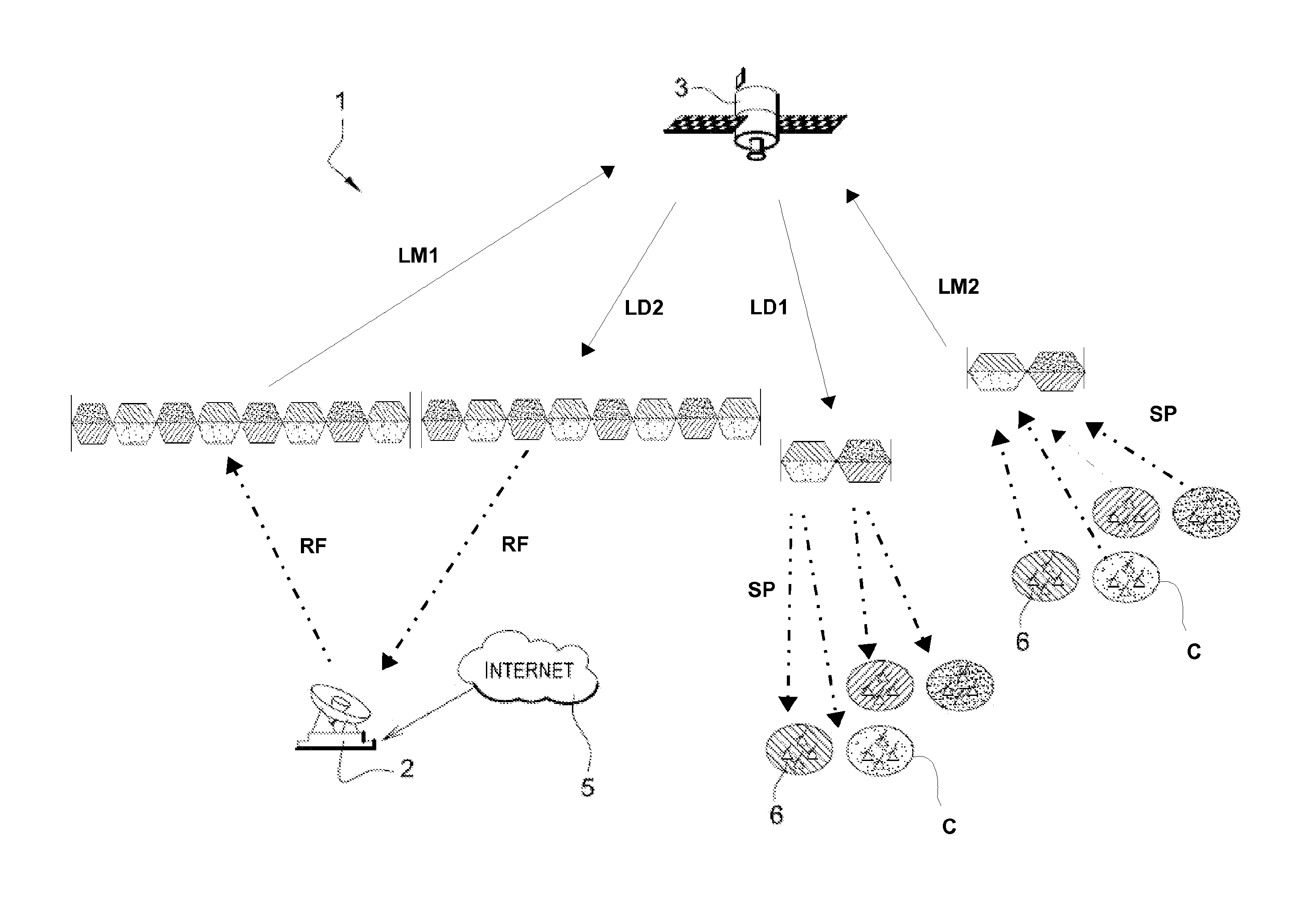
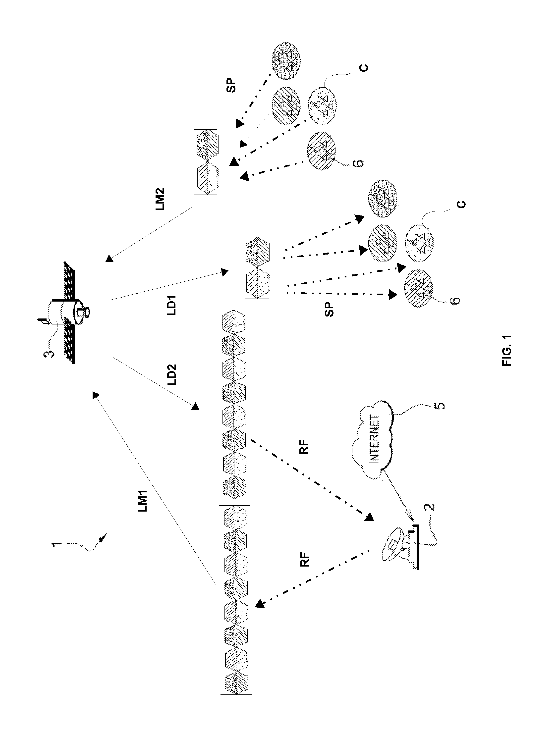
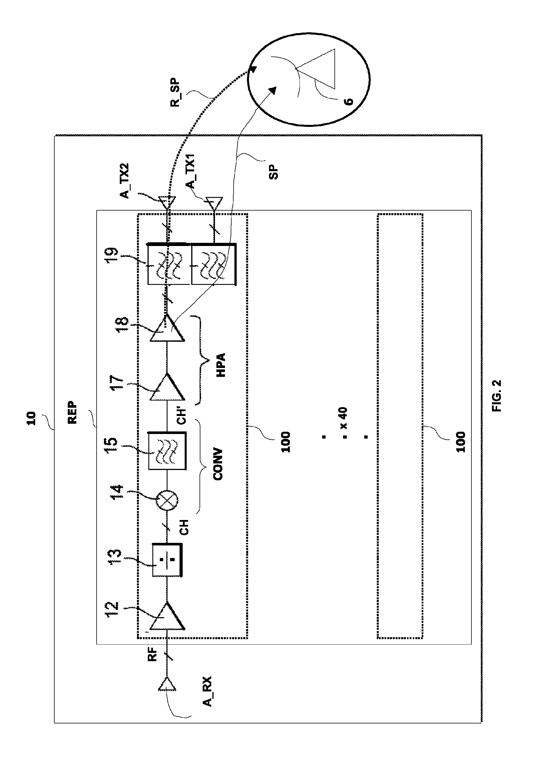
[0179]In the case of external spatial isolation of a half-dell (Dc=0.5), a terrestrial terminal 6 positioned in a green cell, cell C33 for example, will receive:[0180]a first regenerated radiofrequency signal SP33 (dashed line) destined for said green cell; and[0181]a signal replica R_SP33 filtered by the primary lobe Lb1′ (solid line) of the radiation of the antenna which transmits in the direction of the non-adjacent yellow cell C21.

[0182]The replica of the signal R_SP33 will be filtered by this primary lobe Lb1′ instead of by the main lobe Lb0′. Filtering (rejection of the filter) is thus more substantial and therefore the replica of the signal received by the terminal 6 for which the regenerated radiofrequency signal SP33 is destined will be weaker.

[0183]Thus, in the case of external spatial isolation of half cell diameter, if the terminal 6 is located next to the cell and is at a border frequency F2 (described further below) of a channel CH′, the reduction in ...

case b

[0185) C33 and C25

[0186]In the case of external spatial isolation of 1.3 times cell diameter (Dc=1.3), a terrestrial terminal 6 positioned in a green cell, cell C33 for example, will receive:[0187]a first regenerated radiofrequency signal SP33 destined for said green cell; and[0188]a signal replica R_SP33 filtered by a secondary lobe Lb2′ of the radiation of the antenna which transmits in the direction of the non-adjacent yellow cell C25.

[0189]The replica of the signal R_SP33 will be filtered by this secondary lobe Lb2′ instead of by the main lobe Lb0′ or the primary lobe Lb1′. Filtering (rejection of the filter) is thus more substantial and therefore the replica of the signal received by the terminal 6 for which the regenerated radiofrequency signal SP33 is destined will be weaker.

[0190]Thus, in the case of external spatial isolation of cell diameter Dc=1.3, if the terrestrial terminal 6 is located next to the cell and is at a border frequency F2 (described further below) of a chan...


PUM


Abstract

A payload includes one or more antennas for receiving polarized radiofrequency signals; a device for regenerating radiofrequency signals by filtering, frequency transposition, and amplification; and antennas for transmitting the regenerated radiofrequency signals to one or more terrestrial terminals. The radiofrequency signal regeneration device includes a plurality of regeneration channels, each channel consisting of an amplification device capable of amplifying two radiofrequency signals having separate frequency bands and the transmission antennas associated with a regeneration chain are capable of transmitting two regenerated radiofrequency signals having orthogonal polarization directions and intended for cells belonging to a single cell layout that uses at least two separate frequency bands and two separate polarizations.

Description

CROSS REFERENCE TO RELATED APPLICATIONS[0001]This application is the U.S. National Stage of PCT / EP2010 / 064184, filed Sep. 24, 2010, which in turn claims priority to French Patent Application No. 0956616, filed Sep. 24, 2009, the entire contents of all applications are incorporated herein by reference in their entireties.TECHNICAL FIELD OF THE INVENTION[0002]The present invention relates to a forward link payload for a multi-beam satellite, a forward link allowing receipt of radiofrequency signals from at least one main terrestrial station so as to re-transmit said signals to at least one terrestrial terminal, said payload comprising:[0003]one or more reception antennas for receiving polarised radiofrequency signals;[0004]a regeneration device for regenerating radiofrequency signals by filtering, frequency transposition and amplification; and[0005]transmission antennas for transmitting the regenerated radiofrequency signals to one or more terrestrial terminals, each signal being dest...

Claims


Application Information

Patent Timeline
Patent Type & Authority Patents(United States)
IPC IPC(8): H04B7/185H04B7/204
CPCH04B7/18515H04B7/2041
Inventor LANCE, EMMANUELFENECH, HECTOR
Owner EUTELSAT
Features
  • R&D
  • Intellectual Property
  • Life Sciences
  • Materials
  • Tech Scout
  • Unparalleled Data Quality
  • Higher Quality Content
  • 60% Fewer Hallucinations
Learn More