Micro-projection device with antispeckle vibration mode

a technology of vibration mode and projection device, which is applied in the direction of picture reproducers, picture reproducers using projection device, instruments, etc., can solve the problems of affecting the visual comfort of the viewer, causing constructive and destructive interference, and loss of image quality, etc., and achieves the effect of reducing or suppressing speckles

Active Publication Date: 2015-09-08
GOOGLE LLC
View PDF18 Cites 0 Cited by
  • Summary
  • Abstract
  • Description
  • Claims
  • Application Information

AI Technical Summary

Benefits of technology

[0013]A further aim of the invention is to provide such method and device for reducing or suppressing speckle, which offers more possibilities for integration with pre-existing laser micro-projection systems without requiring important modifications.
[0036]The method provides an anti-speckle effect for an observer eye or a sensor receiving the generated illumination.

Problems solved by technology

When the light hits the surface, it creates constructive and destructive interference.
In addition to a loss of image quality, visual comfort of the viewer may also be affected.
The resulting systems are complex, expensive, and involve very specific hardware material.
This solution involves a complex and expensive component, the rotating refracting device.
This solution involves a complex and expensive component, the oscillating refractive element.
This arrangement involves a complex and expensive optical system.

Method used


Image

  • Micro-projection device with antispeckle vibration mode
  • Micro-projection device with antispeckle vibration mode
  • Micro-projection device with antispeckle vibration mode

Examples


Embodiment Construction

[0047]For clarity, as is generally the case in representation of micro-systems, the various figures are not drawn to scale.

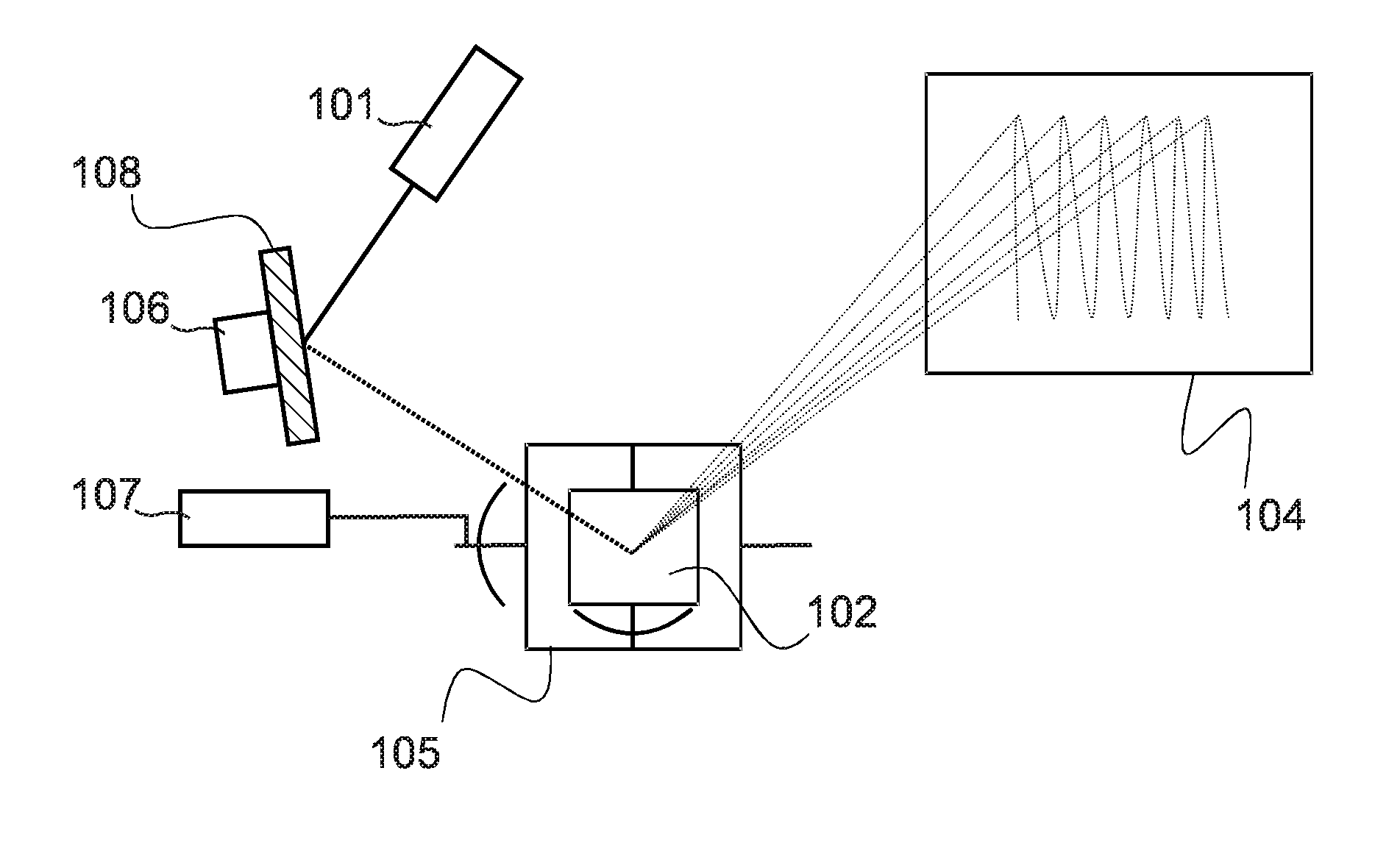
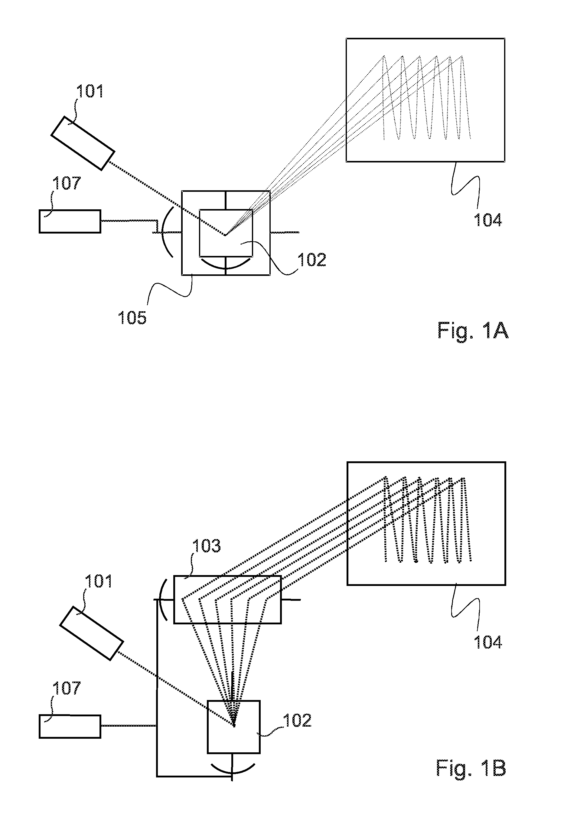
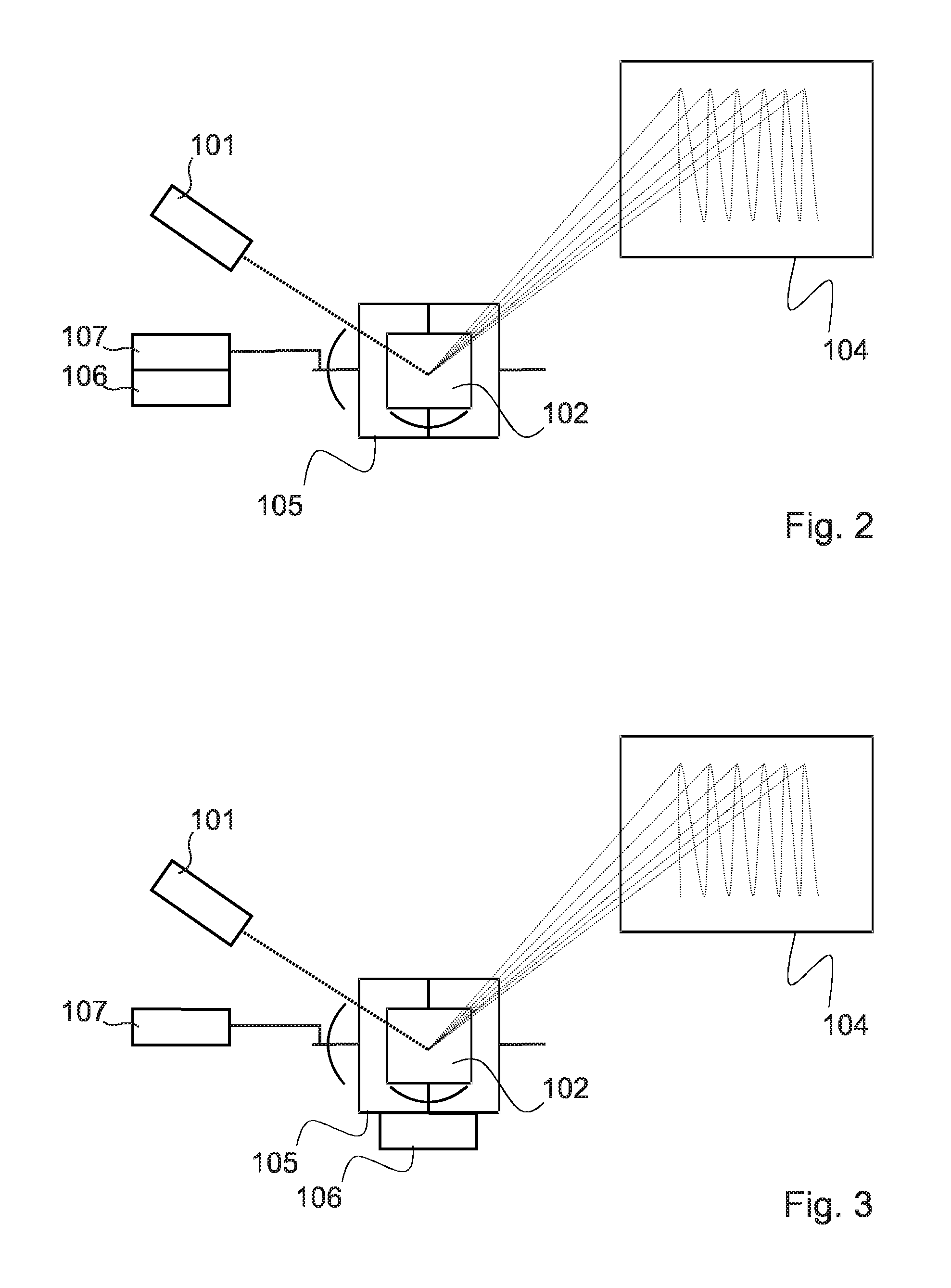
[0048]Micro-Electro-Mechanical-Systems (MEMS) in the form of scanning or moving micro-mirrors are currently being used for projection purposes. The projection can either be done using a single mirror moving along two central and perpendicular axis (two degrees of freedom 2DOF) as shown in FIG. 1A, or two mirrors moving along a central axis (one degree of freedom 1 DOF) both placed at 90 degrees one to each other as shown in FIG. 1B. In FIG. 1A, the image is created by centering a collimated laser beam produced by laser 101 in the middle of the 2DOF micro-mirror surface 102 within the frame 105. The laser beam is reflected and deviated in two directions, so as to project a scanned image on the projection surface 104.

[0049]In FIG. 1B, the projected image is created by centering a collimated laser beam on the first 1DOF micro-mirror surface 102. The laser is reflec...


PUM


Abstract

A micro-projection system for projecting light on a projection surface, comprising: —at least one coherent light source (101); —optical elements (102, 108, 109) in the optical path between said coherent light source and said projection surface; —said optical elements including at least one reflective member (102) actuated by a drive signal for deviating light from said light source so as to scan a projected image onto said projecting surface; —said optical elements including at least one vibrating element (102) actuated by a vibrating signal so as to reduce speckle onto said projecting surface. The corresponding method for reducing speckle is also provided.

Description

[0001]This application is a National Phase Filing of PCT / EP2010 / 055761, filed Apr. 28, 2010, the subject matter of which is incorporated herein by reference in its entirety.FIELD OF THE INVENTION[0002]The present invention relates to a micro-projection system comprising at least one coherent light source, such as laser, and optical elements in the optical path between the coherent light source and the projection surface. It also relates to a method for reducing speckle in such micro-projection systems.BACKGROUND OF THE INVENTION[0003]Speckle is a phenomenon created with laser light sources, due to the fact that laser light is coherent. Parallels and synchronized wavefronts simultaneously hit the projection surface. When the light hits the surface, it creates constructive and destructive interference. The first category of interference induces an image deterioration that is often visible by human eye and / or by sensors. In addition to a loss of image quality, visual comfort of the vie...

Claims


Application Information

Patent Timeline
Patent Type & Authority Patents(United States)
IPC IPC(8): G03B21/28H04N9/31G02B26/10G02B27/48G02B26/08G03B21/20
CPCG03B21/2033G02B26/0833G02B26/105G02B27/48H04N9/3129
Inventor KILCHER, LUCIOABELE, NICOLASKHECHANA, FAOUZI
Owner GOOGLE LLC
Why Eureka
Try Eureka