Micro-projection device with anti-speckle imaging mode

a technology of micro-projection device and imaging mode, which is applied in the direction of picture reproducers, picture reproducers using projection devices, instruments, etc., can solve the problems of affecting the visual comfort of the viewer, causing constructive and destructive interference, and loss of image quality, etc., and achieves the effect of reducing or suppressing speckles

Active Publication Date: 2015-04-07
GOOGLE LLC
View PDF29 Cites 1 Cited by
  • Summary
  • Abstract
  • Description
  • Claims
  • Application Information

AI Technical Summary

Benefits of technology

[0013]A further aim of the invention is to provide such method and device for reducing or suppressing speckle, which offers more possibilities for integration with pre-existing laser micro-projection systems without requiring important modifications.
[0036]In a further embodiment, involving the pixels of a plurality of successive frames, at least some entire frames are moved with respect to others. This embodiment is particularly simple to implement.

Problems solved by technology

When the light hits the surface, it creates constructive and destructive interference.
In addition to a loss of image quality, visual comfort of the viewer may also be affected.
The resulting systems are complex, expensive, and involve very specific hardware material.
This solution involves a complex and expensive component, the rotating refracting device.
This solution involves a complex and expensive component, the oscillating refractive element.
This arrangement involves a complex and expensive optical system.

Method used


Image

  • Micro-projection device with anti-speckle imaging mode
  • Micro-projection device with anti-speckle imaging mode
  • Micro-projection device with anti-speckle imaging mode

Examples


first embodiment

[0052]Depending on the embodiment, a pixel displacement unit 106 generates a displacement of a pixel, or a plurality of pixels, for instance a pixel line or column, or an entire image frame. For instance, in a first embodiment, one pixel is moved randomly or according to a given pattern with respect to the others. A displacement of substantially ½ to 1 / 100 of the pixel size, advantageously around 1 / 10 of the pixel size, provides positive results. In a variant, complete lines or columns of pixels are displaced relative to other lines or columns.

[0053]In another embodiment, a complete image frame is displaced or moved relative to other frames, either randomly or according to a defined way.

[0054]The pixels or frames displacements enable to average the light emissions. For an observer eye placed in a way to look at the projection image, the processed light provides an anti-speckle effect such that perceived speckle is reduced or suppressed. A similar effect is also provided for a sensor...

second embodiment

[0065]FIG. 7c presents a second embodiment involving displacements of entire image frames. Successive frames 600, 601, 602 are moved with respect to the others, as shown in FIG. 8b.

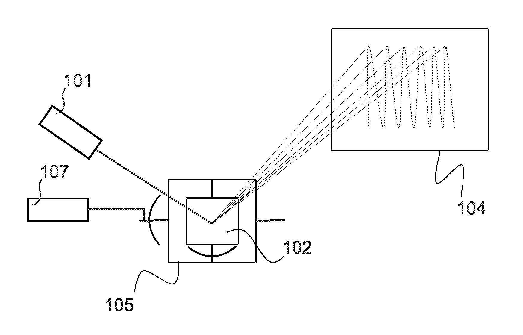
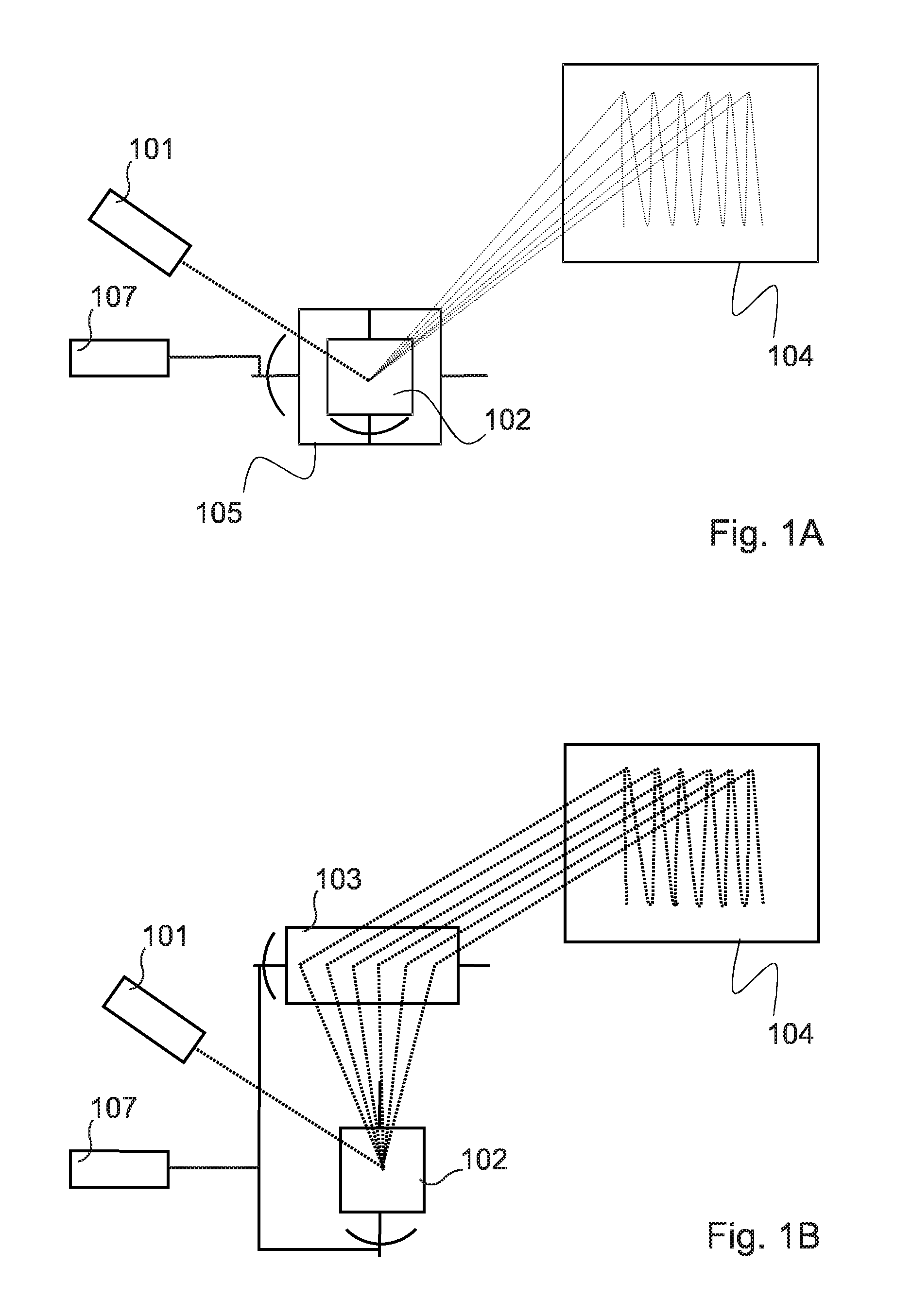
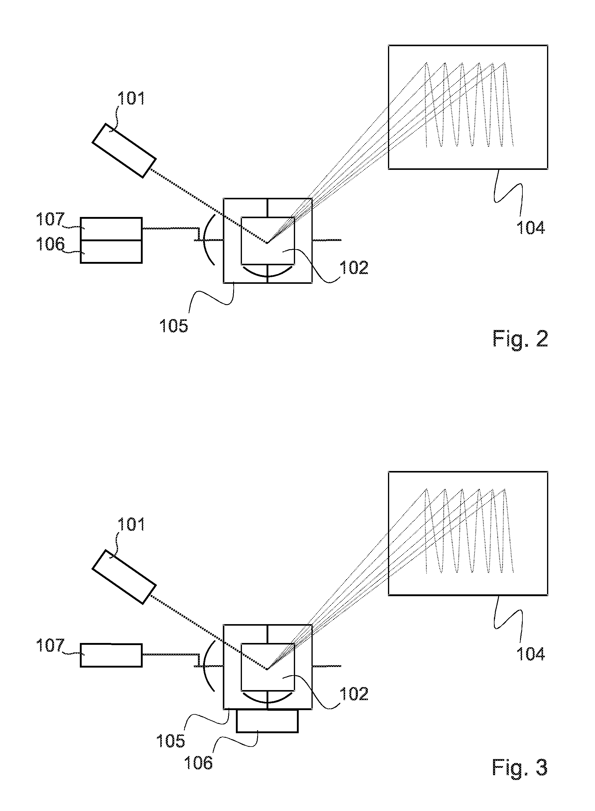
[0066]Pixel displacements may be generated according to several different approaches. First, a pixel displacement unit 106 is coupled to the scanning mirror drive unit 107, which sends a drive signal to the scanning mirror 102 with superposed and synchronized displacement signal. In a second approach, the pixel displacement unit 106 is mechanically connected to an optical element, such as a scanning-mirror, as shown in FIG. 3, to an anti-speckle mirror or membrane 108, as shown in FIG. 4, to an anti-speckle optical element 109, as shown in FIG. 5, or to the light source 101, as shown in FIG. 6. The pixels or frames displacements provide an anti-speckle effect.

[0067]In a further approach, pixel displacement is achieved by pulsing the laser at unevenly spaced instants in time, i.e., with a variable phase. ...


PUM


Abstract

A micro-projection system for projecting light on a projection surface (104), comprising: —at least one coherent light source (101); —optical elements (102, 108, 109) in the optical path between said coherent light source and said projection surface; —said optical elements including at least one reflective member (102) actuated by a drive signal for deviating light from said light source so as to scan a projected image onto said projecting surface; —said optical elements including at least one pixel displacement unit (106) for providing a displacement signal synchronized with the image scanning signal so as to reduce speckle onto said projecting surface. The corresponding method for reducing speckle is also provided.

Description

[0001]This application is a National Phase Filing of PCT / EP2010 / 055763, filed Apr. 28, 2010, the subject matter of which is incorporated herein by reference in its entirety.FIELD OF THE INVENTION[0002]The present invention relates to a micro-projection system comprising at least one coherent light source, such as laser, and optical elements in optical path between the light source and a projection surface. It also relates to a method for reducing speckle in a laser micro-projection system.BACKGROUND OF THE INVENTION[0003]Speckle is a phenomenon created with laser light sources, due to the fact that laser light is coherent. Parallels and synchronized wavefronts simultaneously hit the projection surface. When the light hits the surface, it creates constructive and destructive interference. The first category of interference induces an image deterioration that is often visible by human eye and / or by sensors. In addition to a loss of image quality, visual comfort of the viewer may also ...

Claims


Application Information

Patent Timeline
Patent Type & Authority Patents(United States)
IPC IPC(8): G03B21/14G02B27/48G02B26/08G02B26/10G03B21/16H04N9/31
CPCG02B27/48G02B26/0833G02B26/101H04N9/3129G03B21/16
Inventor KILCHER, LUCIOKHECHANA, FAOUZIABELE, NICOLAS
Owner GOOGLE LLC
Why Eureka
Try Eureka