Optical MEMS scanning micro-mirror with Anti-speckle cover

a micro-mirror and optical technology, applied in the field of optical mems scanning micro-mirrors, can solve the problems of affecting the visual comfort of the viewer, causing constructive and destructive interference, loss of image quality, etc., and achieve the effect of reducing or suppressing speckles

Inactive Publication Date: 2013-10-24
GOOGLE LLC
View PDF5 Cites 18 Cited by
  • Summary
  • Abstract
  • Description
  • Claims
  • Application Information

AI Technical Summary

Benefits of technology

[0012]A general aim of the invention is therefore to provide an improved device and method for reducing or suppressing speckle in a laser micro-projection system.

Problems solved by technology

When the light hits the surface, it creates constructive and destructive interference.
In addition to a loss of image quality, visual comfort of the viewer may also be affected.
The resulting systems are complex, expensive, and involve very specific hardware material.
This solution involves a complex and expensive component, the rotating refracting device.
This solution provides an efficient auto-focus system, but is not adapted to reduce speckle.
This solution involves symmetrical stress, which is not suited for speckle reduction.

Method used


Image

  • Optical MEMS scanning micro-mirror with Anti-speckle cover
  • Optical MEMS scanning micro-mirror with Anti-speckle cover
  • Optical MEMS scanning micro-mirror with Anti-speckle cover

Examples


Embodiment Construction

[0069]For clarity, as is generally the case in representation of microsystems, the various figures are not drawn to scale.

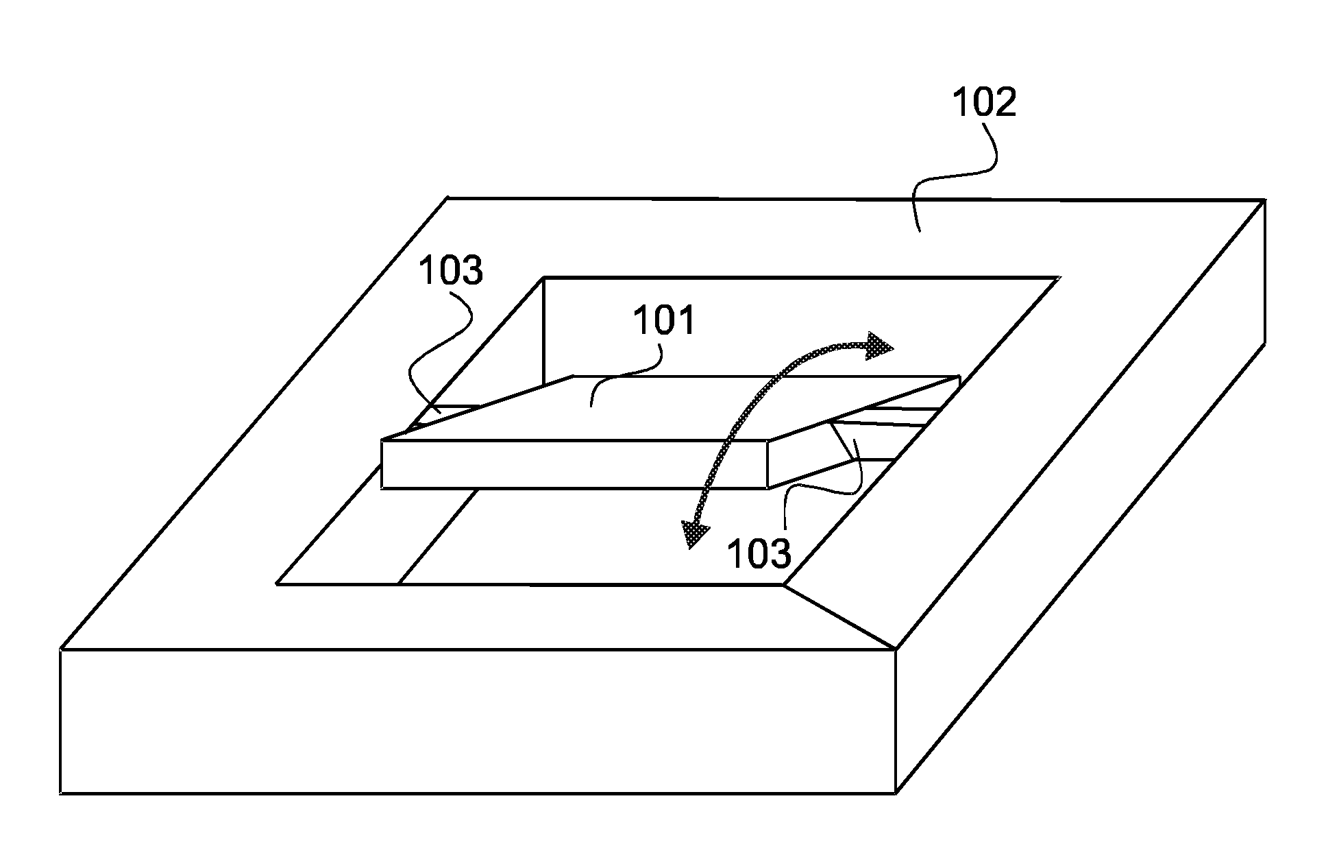
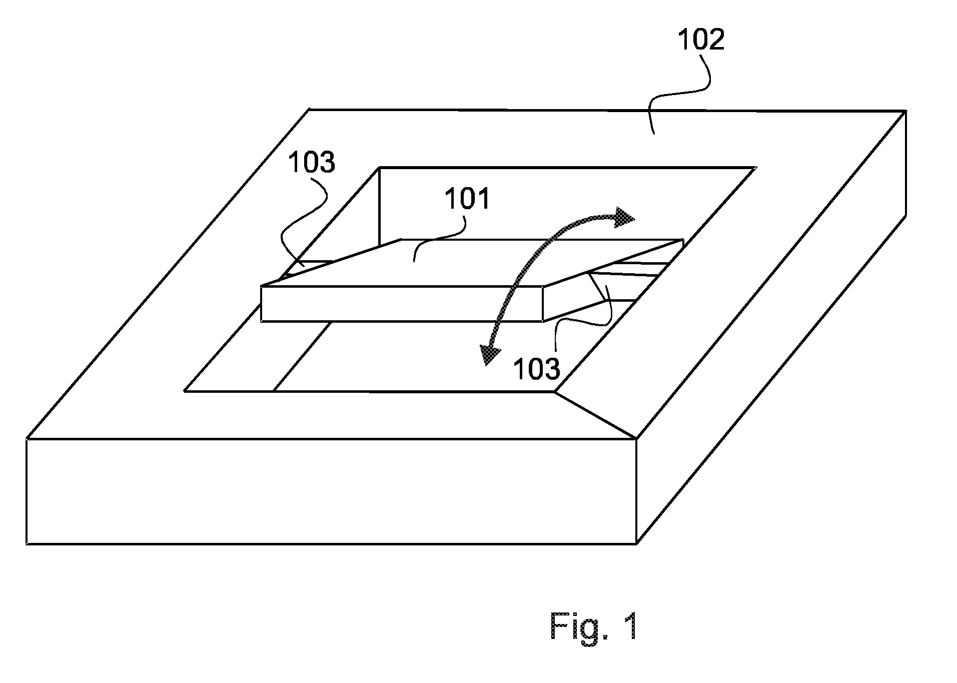
[0070]FIG. 1 presents a typical rectangular MEMS moving micro-mirror 101, anchored to a fix body 102 by two beams 103, and deflected along its central axis.

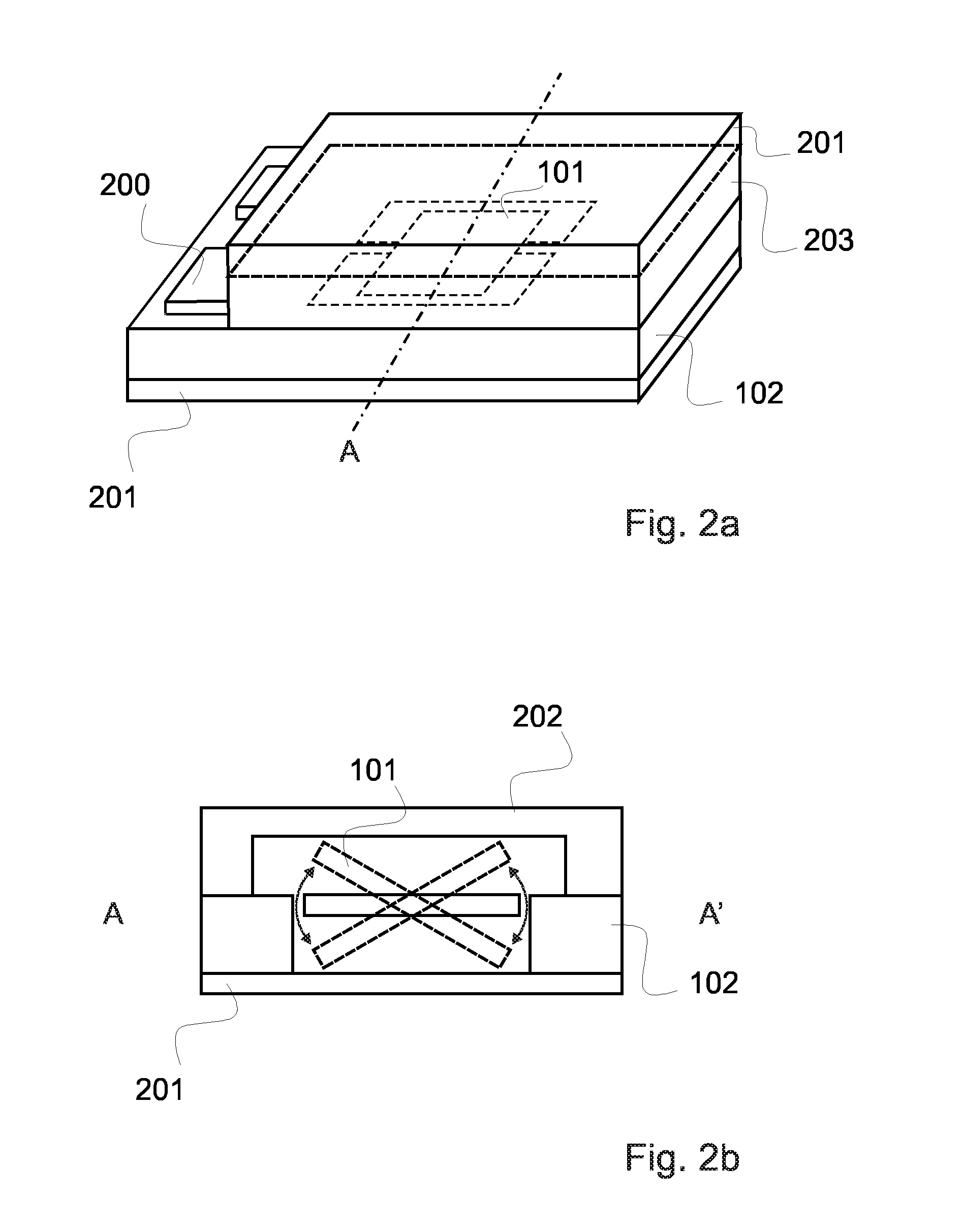
[0071]An example of known type packaged MEMS mirror is presented in FIG. 2A and FIG. 2B, where the MEMS mirror 101 is protected by a package comprising in this example transparent or semi-transparent surfaces 201 and 202 as the incoming light can either come from one side or from two sides of the mirror surfaces.

[0072]The package of the encapsulated MEMS micro-mirror comprises a cap part with an optical window 202 that allows the light to penetrate and reflects on the micro-mirror surface. The cap optical window is typically made of glass such as borosilicate glass (for instance borofloat) or other type of glass, and has usually a flat surface. Micro-mirror surface can also be coated with reflective material s...


PUM

PropertyMeasurementUnit
transparentaaaaaaaaaa
metallicaaaaaaaaaa
reflectionaaaaaaaaaa

Abstract

Optical MEMS scanning micro-mirror comprising: —a movable scanning micro-mirror (101), being pivotally connected to a MEMS body (102) substantially surrounding the lateral sides of the micro-mirror, —a transparent window (202) substantially covering the reflection side of the micro-mirror; —wherein a piezo-actuator assembly (500) and a layer of deformable transparent material (501) are provided on the outer portion of said window (202); —the piezo-actuator assembly (500) being arranged at the periphery of the layer of transparent material (501); —said piezo-actuator assembly (500) and transparent material (501) cooperating so that when actuated, the piezo-actuator assembly (500) causes micro-deformation of the transparent material (501), thereby providing an anti-speckle effect. The invention also provides the corresponding micro-projection system and method for reducing speckle.

Description

FIELD OF THE INVENTION[0001]The present invention relates to an optical MEMS scanning micro-mirror comprising[0002]a movable scanning micro-mirror being pivotally connected to a MEMS body substantially surrounding the lateral sides of the micro-mirror, a substrate covering a back face of said mirror and a transparent window substantially covering the reflection side of the micro-mirror. The present invention also relates to a micro-projection system comprising such a micro-mirror, a corresponding method for reducing speckle and a method for manufacturing the optical MEMS scanning mirror.BACKGROUND OF THE INVENTION[0003]Speckle is a phenomenon created with laser light sources, due to the fact that laser light is coherent. Parallels and synchronized wavefronts simultaneously hit the projection surface. When the light hits the surface, it creates constructive and destructive interference. The first category of interference induces an image deterioration that is often visible by human e...

Claims


Application Information

Patent Timeline
Patent Type & Authority Applications(United States)
IPC IPC(8): G02B27/48B81C1/00G03B21/28
CPCG02B27/48G03B21/28B81C1/00G02B5/0215G02B5/0278G02B26/0833G02B26/0875G02B26/105H04N9/3129Y10T29/42
Inventor ABELE, NICOLASKHECHANA, FAOUZI
Owner GOOGLE LLC
Why Eureka
Try Eureka