Light-emitting device, electronic device, and lighting device utilizing phosphorescence

a technology of light-emitting devices and electronic devices, which is applied in the direction of organic semiconductor devices, luminescent compositions, chemistry apparatus and processes, etc., can solve the problems of difficult generation of triplet excited molecules, achieve high efficiency, improve recombination efficiency in the light-emitting layer, and reduce power consumption

Active Publication Date: 2015-09-08
SEMICON ENERGY LAB CO LTD
View PDF71 Cites 20 Cited by
  • Summary
  • Abstract
  • Description
  • Claims
  • Application Information

AI Technical Summary

Benefits of technology

[0021]Note that a phosphorescent organometallic iridium complex having the structure which is represented by General Formula (G1) or (G2) and in which the lowest triplet excited state is formed in the structure is preferable because the phosphorescent organometallic iridium complex can efficiently exhibit phosphorescence.
[0043]Further, a light-emitting device that is a still further embodiment of the present invention includes a light-emitting element in which an EL layer containing the phosphorescent organometallic iridium complex is interposed between a pair of electrodes. Note that one of the pair of electrodes functions as a reflective electrode, the other electrode functions as a semi-transmissive and semi-reflective electrode, and an optical path length between the electrodes is adjusted such that light with wavelengths which differ depending on the light-emitting elements can be emitted. When such a light-emitting element is applied to a light-emitting device (so-called microcavity light-emitting device), emission intensity with a predetermined wavelength in the front direction can be increased, whereby power consumption can be reduced. The above structure is particularly useful in the case of being applied to a color display (image display device) including pixels of three or more colors.

Problems solved by technology

However, the ground state of an ordinary organic compound is a singlet state; therefore, photoexcitation to a triplet excited state is forbidden transition and generation of a triplet excited molecule is difficult.

Method used


Image

  • Light-emitting device, electronic device, and lighting device utilizing phosphorescence
  • Light-emitting device, electronic device, and lighting device utilizing phosphorescence
  • Light-emitting device, electronic device, and lighting device utilizing phosphorescence

Examples


embodiment 1

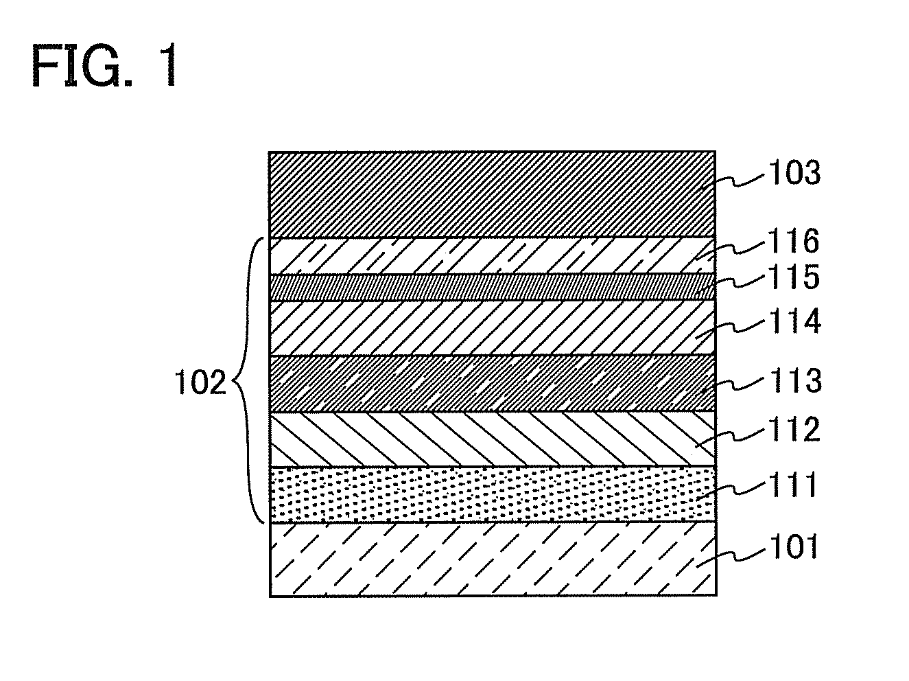
[0082]In this embodiment, as a light-emitting element which can be applied to a light-emitting device utilizing phosphorescence, a light-emitting element in which a phosphorescent organometallic iridium complex is used in a light-emitting layer is described with reference to FIG. 1.

[0083]In a light-emitting element described in this embodiment, as illustrated in FIG. 1, an EL layer 102 including a light-emitting layer 113 is provided between a pair of electrodes (a first electrode (anode) 101 and a second electrode (cathode) 103), and the EL layer 102 includes a hole-injection layer 111, a hole-transport layer 112, an electron-transport layer 114, an electron-injection layer 115, a charge-generation layer (E) 116, and the like in addition to the light-emitting layer 113.

[0084]By application of a voltage to such a light-emitting element, holes injected from the first electrode 101 side and electrons injected from the second electrode 103 side recombine in the light-emitting layer 113...

embodiment 2

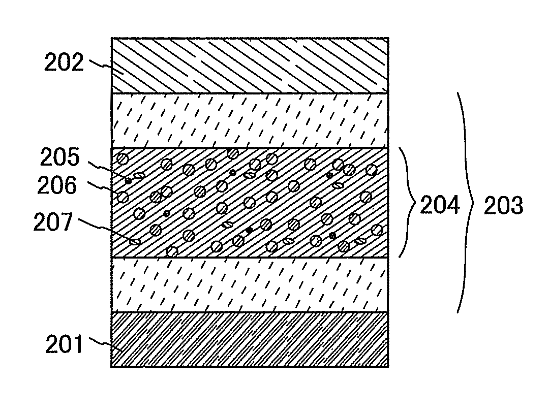
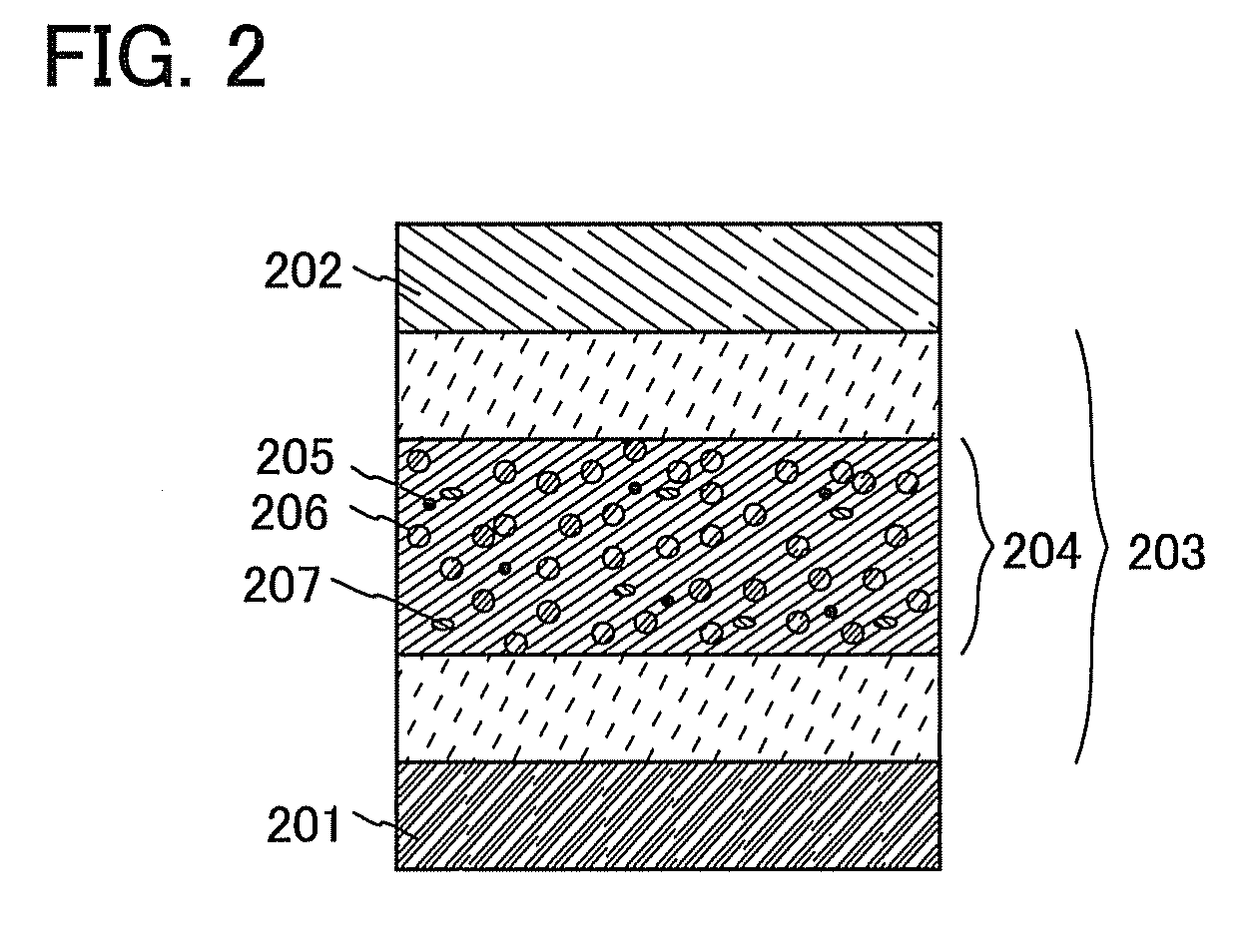
[0122]In this embodiment, as one embodiment of the present invention, a light-emitting element in which two or more kinds of organic compounds as well as a phosphorescent organometallic iridium complex are used for a light-emitting layer is described.

[0123]A light-emitting element described in this embodiment includes an EL layer 203 between a pair of electrodes (an anode 201 and a cathode 202) as illustrated in FIG. 2. Note that the EL layer 203 includes at least a light-emitting layer 204 and may include a hole-injection layer, a hole-transport layer, an electron-transport layer, an electron-injection layer, a charge-generation layer (E), and the like. Note that for the hole-injection layer, the hole-transport layer, the electron-transport layer, the electron-injection layer, and the charge-generation layer (E), the substances described in Embodiment 1 can be used.

[0124]The light-emitting layer 204 described in this embodiment contains a phosphorescent compound 205 using the phosp...

embodiment 3

[0140]In this embodiment, as one embodiment of the present invention, a light-emitting element (hereinafter referred to as tandem light-emitting element) in which a plurality of EL layers are included so as to sandwich a charge-generation layer will be described.

[0141]A light-emitting element described in this embodiment is a tandem light-emitting element including a plurality of EL layers (a first EL layer 302(1) and a second EL layer 302(2)) between a pair of electrodes (a first electrode 301 and a second electrode 304) as illustrated in FIG. 3A.

[0142]In this embodiment, the first electrode 301 functions as an anode, and the second electrode 304 functions as a cathode. Note that the first electrode 301 and the second electrode 304 can have structures similar to those described in Embodiment 1. In addition, although the plurality of EL layers (the first EL layer 302(1) and the second EL layer 302(2)) may have structures similar to those described in Embodiment 1 or 2, any of the EL...


PUM

PropertyMeasurementUnit
internal quantum efficiencyaaaaaaaaaa
visible light transmittanceaaaaaaaaaa
wavelength rangeaaaaaaaaaa

Abstract

A new light-emitting device utilizing phosphorescence is provided. Further, an electronic device and a lighting device which utilize phosphorescence are provided. One embodiment of the present invention is a light-emitting device including a phosphorescent organometallic iridium complex comprising iridium and either pyrimidine having an aryl group at the 4-position or 1,3,5-triazine having an aryl group at the 2-position. One of nitrogen in the pyrimidine or 1,3,5-triazine is coordinated to the iridium. Also, each of the pyrimidine and 1,3,5-triazine has a substituent such as an alkyl group or an aryl group. Further the ortho position of the aryl group which is bonded to the 4-position of the pyrimidine or the 2-position of the 1,3,5-triazine is bonded to the iridium.

Description

BACKGROUND OF THE INVENTION[0001]1. Field of the Invention[0002]One embodiment of the present invention relates to a light-emitting device utilizing phosphorescence. The light-emitting device can emit phosphorescence by including a light-emitting element in which an EL layer contains an organometallic iridium complex capable of converting triplet excited energy into luminescence. Further, one embodiment of the present invention relates to an electronic device and a lighting device which utilize phosphorescence.[0003]2. Description of the Related Art[0004]Organic compounds are brought into an excited state by the absorption of light. Through this excited state, various reactions (photochemical reactions) are caused in some cases, or luminescence is generated in some cases. Therefore, the organic compounds have a wide range of applications.[0005]As one example of the photochemical reactions, a reaction of singlet oxygen with an unsaturated organic molecule (oxygen addition) is known (...

Claims


Application Information

Patent Timeline
Patent Type & Authority Patents(United States)
IPC IPC(8): C09K11/06H01L51/50H01L51/00C09K11/00H01L27/32H01L51/52
CPCH01L51/5016C09K11/06H01L51/0085C09K2211/1007C09K2211/1011C09K2211/1029C09K2211/1044C09K2211/185H01L27/3206H01L27/3209H01L51/5068H01L51/5265H01L51/5278H01L2251/5361H01L2251/5384H10K59/30H10K59/32H10K85/342H10K50/157H10K50/11H10K2101/10H10K50/19H10K2101/90H10K59/876C09K19/3828H01L31/022466H10K85/631H10K50/852
Inventor SEO, SATOSHIINOUE, HIDEKOSEO, HIROMIYAMAGUCHI, TOMOYASHITAGAKI, SATOKOUSHIKUBO, TAKAHIRO
Owner SEMICON ENERGY LAB CO LTD
Why Eureka
Try Eureka