
Micro Display Panels With Integrated Micro-Reflectors

a technology of micro-reflectors and display panels, applied in the field of display panels, can solve the problems of complex illumination optics, reduced projection system efficiency, and inability to transmit or reflect light, so as to reduce the light crosstalk between adjacent pixels, improve projection brightness and contrast, and reduce the divergence of ligh

Active Publication Date: 2018-03-29
JADE BIRD DISPLAY SHANG HAI LTD
View PDF4 Cites 69 Cited by
  • Summary
  • Abstract
  • Description
  • Claims
  • Application Information

AI Technical Summary

Benefits of technology

The disclosed patent provides a micro display panel with a high-brightness, high-contrast, and power-efficient display using micro-reflectors integrated with the micro-LEDs. This reduces the divergence of light and crosstalk between adjacent pixels, improving the projection brightness and contrast and reducing power consumption. The micro-reflectors also improve the light-emission directionality of the display, protecting user privacy.

Problems solved by technology

However, the part of the light that is not transmitted or reflected is lost, which reduces the efficiency of the projection system.
Furthermore, to provide the collimated light, complex illumination optics is required to collect divergent light emitted from the light source.
The illumination optics not only causes the system to be bulky but also introduces additional optical loss into the system, which further impacts the performance of the system.
However, the light emitted by the micro-LED is generated from spontaneous emission and is thus not directional, resulting in a large divergence angle.
The large divergence angle can cause various problems in an LED display.
This significantly reduces the efficiency and brightness of the AMLED micro display based projection system.
As another example, due to the large divergence angle, the light emitted by one micro-LED pixel can illuminate its adjacent pixels, resulting in light crosstalk between pixels, loss of sharpness, and loss of contrast.
Due to their geometry, micro-LEDs almost always produce a significant amount of light emitted at these oblique angles, which cannot be effectively collected by the corresponding microlens on top.
In addition to wasting power, obliquely emitted light may also be collected by the adjacent microlens, causing cross-talk and reducing the image contrast.

Method used


Image

  • Micro Display Panels With Integrated Micro-Reflectors
  • Micro Display Panels With Integrated Micro-Reflectors
  • Micro Display Panels With Integrated Micro-Reflectors

Examples


Embodiment Construction

[0032]The figures and the following description relate to preferred embodiments by way of illustration only. It should be noted that from the following discussion, alternative embodiments of the structures and methods disclosed herein will be readily recognized as viable alternatives that may be employed without departing from the principles of what is claimed.

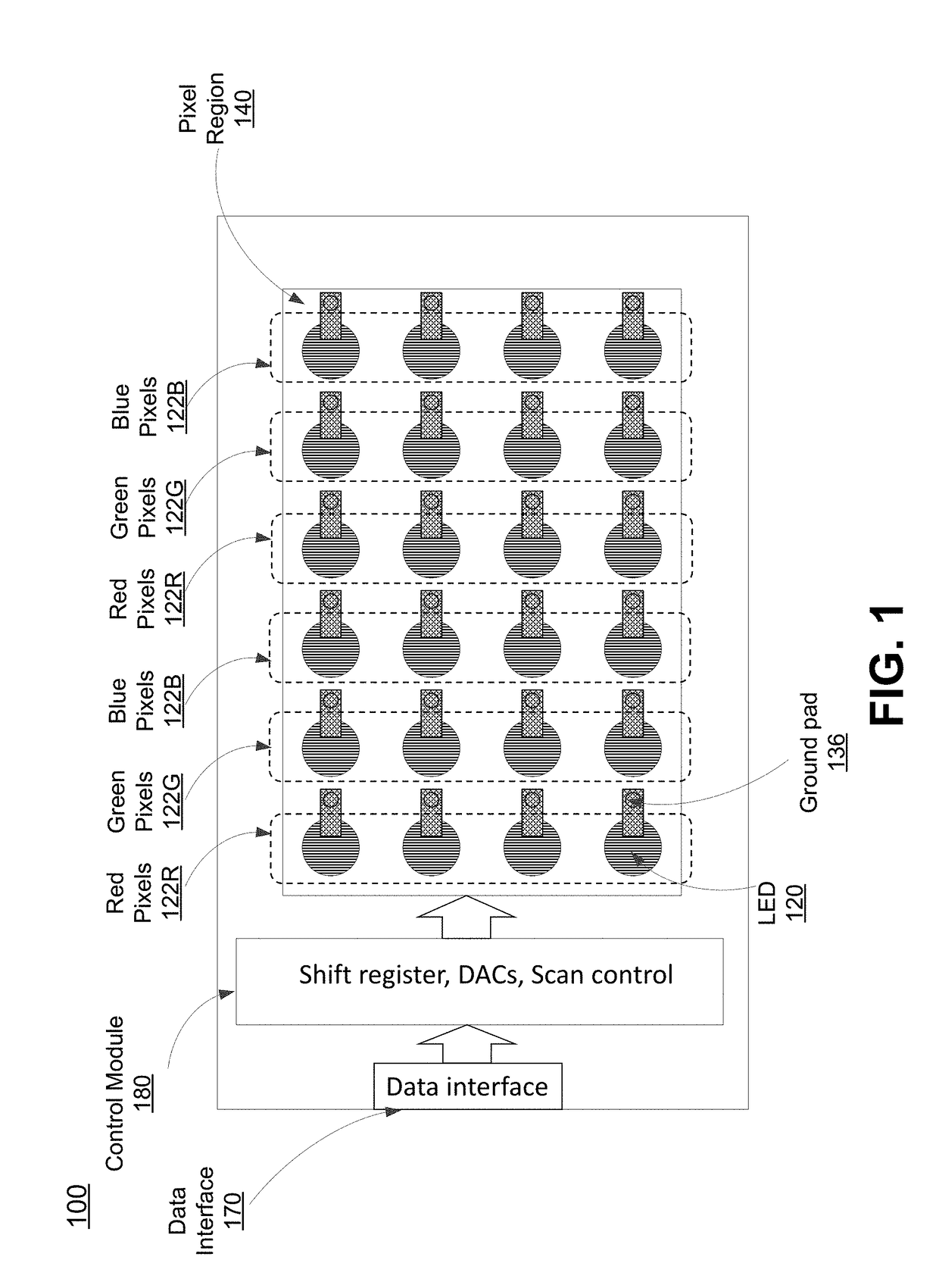
[0033]FIG. 1 is a top view of an example LED display panel 100, according to one embodiment. The display panel 100 includes a data interface 170, a control module 180 and a pixel region 140. The data interface 170 receives data defining the image to be displayed. The source(s) and format of this data will vary depending on the application. The control module 180 receives the incoming data and converts it to a form suitable to drive the pixels in the display panel. The control module 180 may include digital logic and / or state machines to convert from the received format to one appropriate for the pixel region 140, shift registe...


PUM


Abstract

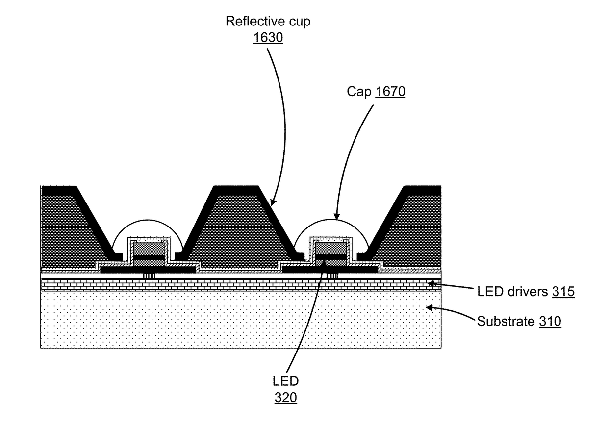
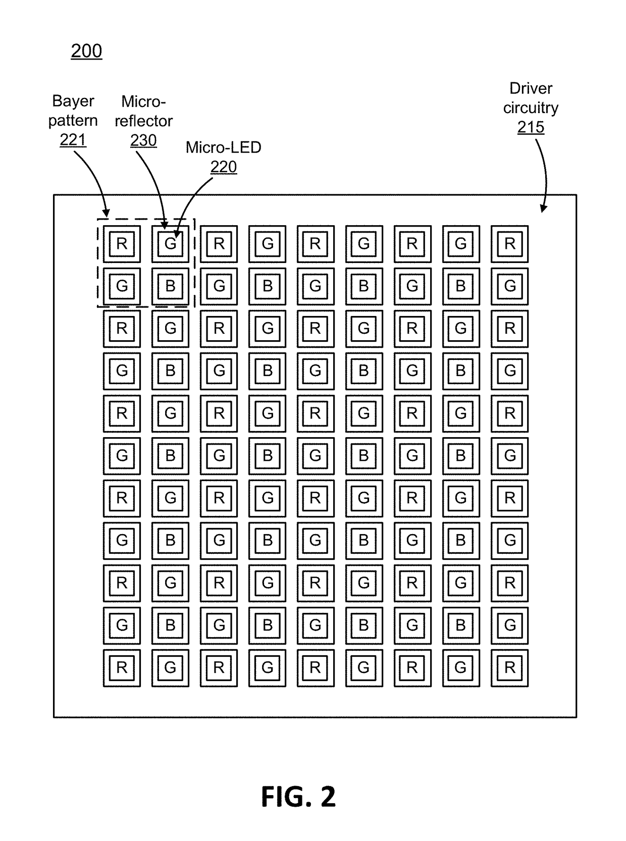
A display panel with integrated micro-reflectors. The display panel also includes an array of pixel light sources (e.g., micro-LEDs) electrically coupled to corresponding pixel driver circuits (e.g., FETs). The micro-LEDs produce light and the micro-reflectors reduce the divergence of the light produced by the micro-LEDs. Different designs are possible. The micro-reflectors can have different shapes, include the shape of their sidewalls and the shape of their plan cross-section. The array schemes can also vary, including the number of LEDs per micro-reflector. Different fabrication approaches are also possible. In one approach, a support structure is integrated between micro-LEDs. The sides of the support structure are reflective and serve as the reflective sidewalls of the micro-reflector. Alternately, the LED mesa itself can serve as the support structure.

Description

CROSS-REFERENCE TO RELATED APPLICATION(S)[0001]This application claims priority under 35 U.S.C. § 119(e) to U.S. Provisional Patent Application Ser. No. 62 / 399,203, “On-chip Microstructuring for Compact, High Brightness Micro-Display and Projection,” filed Sep. 23, 2016. The subject matter of all of the foregoing is incorporated herein by reference in their entirety.BACKGROUND1. Technical Field[0002]This disclosure relates generally to display panels, especially display panels based on micro-LED arrays, integrated with micro-optics.2. Description of Related Art[0003]Digital display technology has become one of the largest branches in the field of modern electronics and optoelectronics and generates demands in various applications where an image forming function is needed. Among those applications, projection-based display, which has the potential of generating a large size image with low cost, is of great interest.[0004]In a conventional projection system based on a passive imager d...

Claims


Application Information

Patent Timeline
Patent Type & Authority Applications(United States)
IPC IPC(8): G09G3/32H01L33/60
CPCG09G3/32G09G2300/0426H01L33/60G09G3/2003G09G2300/0452H01L25/0753
Inventor CHEN, YIJINGOU, FANGCHONG, WING CHEUNGZHANG, LEILI, QIMING
Owner JADE BIRD DISPLAY SHANG HAI LTD
Learn More