
Vehicle seat

a technology for vehicles and seats, applied in the field of vehicles, can solve the problems of occupants who cannot but experience the hardness of touching, deterioration of the quality of the vehicle seat, etc., and achieve the effects of easy adjustment of rigidity, high rigidity, and the same softness

Active Publication Date: 2015-09-15
TOYOTA BOSHOKU KK +1
View PDF17 Cites 0 Cited by
  • Summary
  • Abstract
  • Description
  • Claims
  • Application Information

AI Technical Summary

Benefits of technology

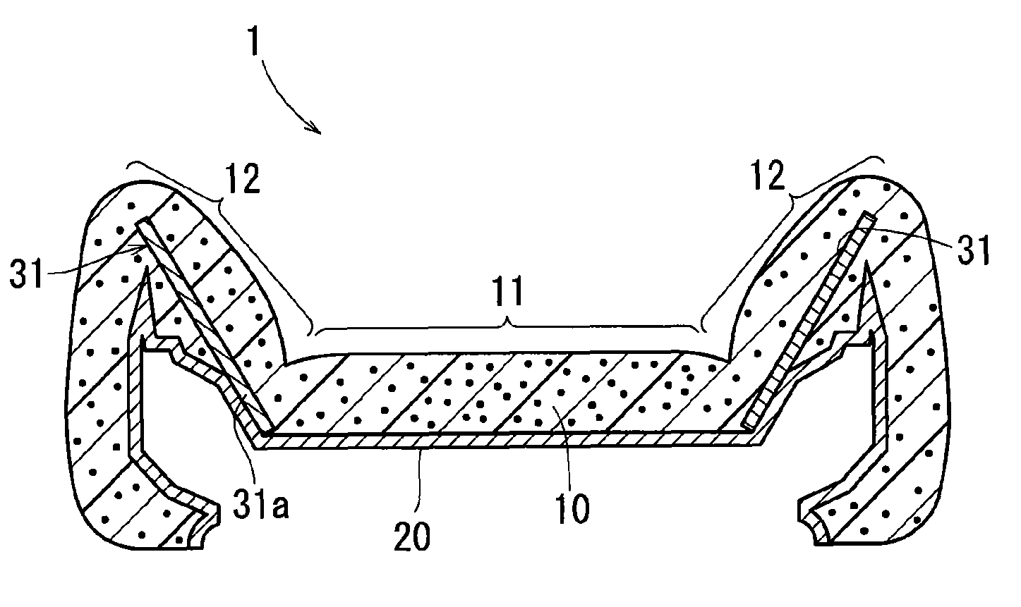
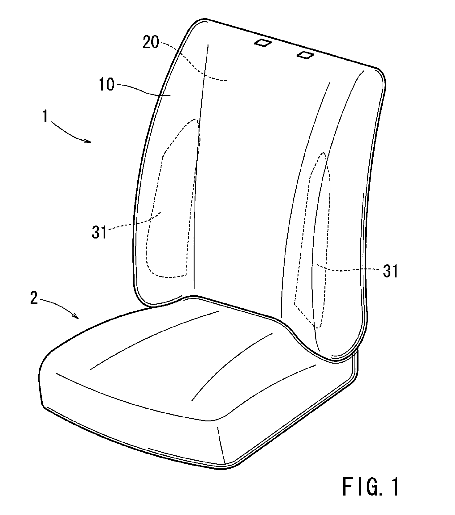
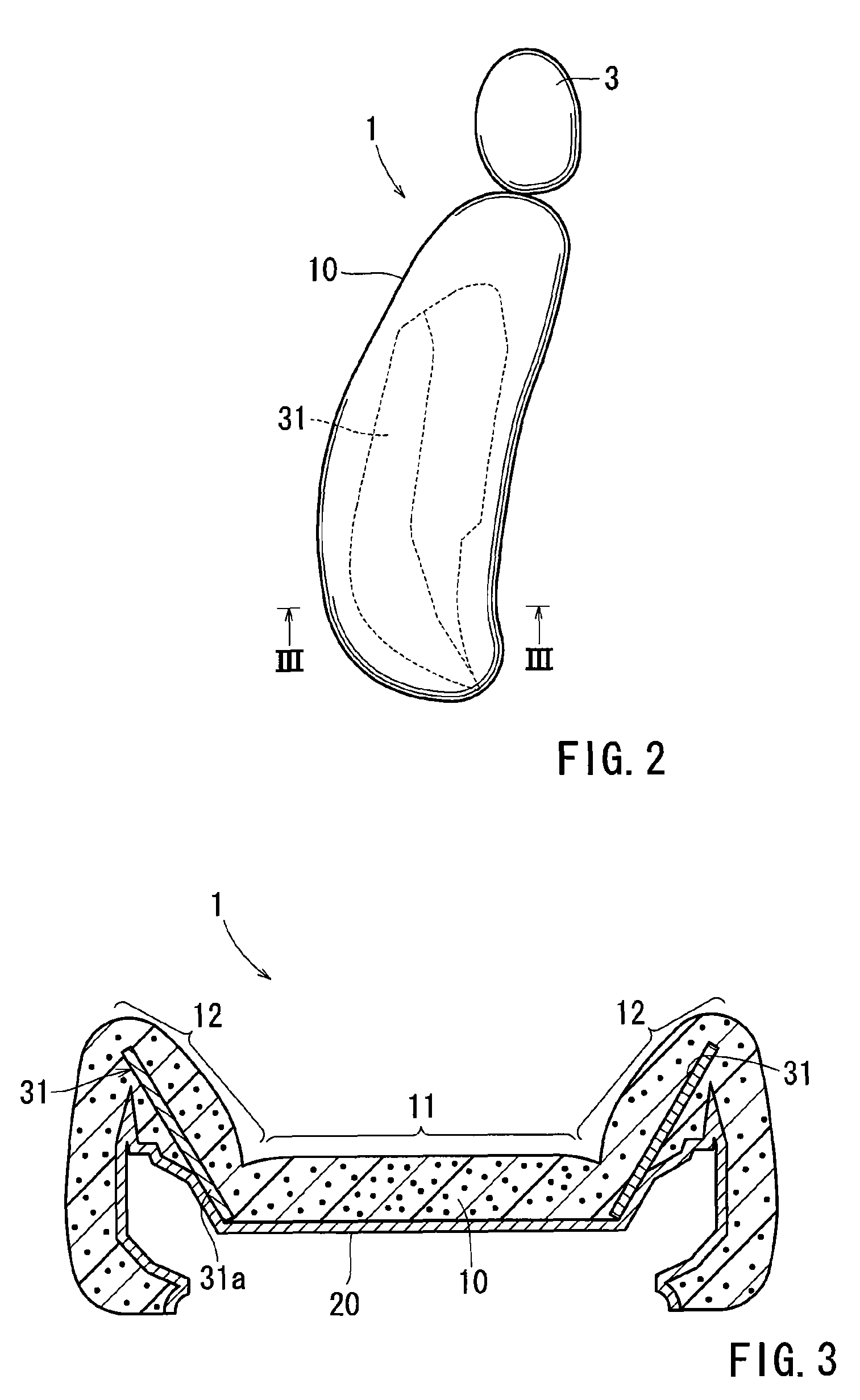
The present invention relates to a vehicle seat with a cushion pad, surface member, and rigid member. The cushion pad has a side support portion that protrudes from the main portion to support the occupant's side. The surface member is provided on the cushion pad's surface, and the rigid member is provided inside the side support portion. The rigid member is of higher rigidity than the cushion pad and protrudes in the same direction as the side support portion. The rigid member contacts the surface member and is integrated with it, eliminating the need for a separate support member. The appearance of the surface member on the side support portion does not adversely affect the cushion pad. The rigid member may be cloth with woven threads, allowing for easy adjustment of rigidity and thickness. The surface member may have a portion corresponding to the main portion of the cushion pad, which is fixed inside the foaming mold, eliminating the need for a separate support for the rigid member prior to foam-molding of the cushion pad. This improves productivity.

Problems solved by technology

However, when the side support portions exhibit generally high rigidity, the occupant cannot but experience their hardness when he touches them.
The deficient portion appears on the surface of the cushion pad, resulting in deterioration in the quality of the vehicle seat.

Method used


Image

  • Vehicle seat
  • Vehicle seat
  • Vehicle seat

Examples


Embodiment Construction

[0022]Each of the additional features and teachings disclosed above and below may be utilized separately or in conjunction with other features and teachings to provide improved vehicle seats. Representative examples of the present invention, which utilize many of these additional features and teachings both separately and in conjunction with one another, will now be described in detail with reference to the attached drawings. This detailed description is merely intended to teach a person of ordinary skill in the art further details for practicing preferred aspects of the present teachings and is not intended to limit the scope of the invention. Only the claims define the scope of the claimed invention. Therefore, combinations of features and steps disclosed in the following detailed description may not be necessary to practice the invention in the broadest sense, and are instead taught merely to particularly describe representative examples of the invention. Moreover, various featur...


PUM


Abstract

Embodiments of the present invention may include a vehicle seat having a cushion pad, a surface member, and a rigid member. The cushion pad may be equipped with a main portion for supporting an occupant, and a side support portion provided on a side of the main portion. The side support portion may protrude from the main portion so as to support the occupant. The surface member is provided on a surface of the cushion pad. The rigid member is provided inside the side support portion of the cushion pad. The rigid member is of higher rigidity than the cushion pad, and protrudes in the same direction in which the side support portion protrudes. The rigid member has an end portion contacting the surface member.

Description

[0001]This application claims priority to Japanese patent application serial number 2012-107546, the contents of which are incorporated herein by reference.BACKGROUND OF THE INVENTION[0002]1. Field of the Invention[0003]Embodiments of the present invention relate to vehicle seats.[0004]2. Description of the Related Art[0005]A vehicle seat generally has a cushion pad placed on a seat frame. The cushion pad is equipped with a main portion forming the seating surface for an occupant seated thereon, and side support portions provided on the sides of the main portion. The side support portions protrude from the main portion so as to support the sides of the body of the occupant.[0006]The side support portions of the vehicle seat are of higher rigidity than the main portion, and are not subject to deformation with respect to external forces. Thus, the side support portions can effectively support the occupant, and suppress the discomfort due to side wires provided in the seat frame. Howev...

Claims


Application Information

Patent Timeline
Patent Type & Authority Patents(United States)
IPC IPC(8): B60N2/64B60N2/68B60N2/44B60N2/90
CPCB60N2/646B60N2/449B60N2/68B60N2/986B60N2/7017
Inventor MURATA, YOSHIYUKIHAYASHIDA, TETSUOIWASAWA, TOSHIO
Owner TOYOTA BOSHOKU KK
Learn More