System and methods for correcting spinal deformities

a spinal deformity and spinal system technology, applied in the field of spinal deformity correction systems and methods, can solve the problems that the d or tsrh technique failed to correct the axially unbalanced vertebrae, and achieve the effect of superior rigidity and maximum spinal deformity correction

Active Publication Date: 2015-09-22
SEASPINE
View PDF54 Cites 15 Cited by
  • Summary
  • Abstract
  • Description
  • Claims
  • Application Information

AI Technical Summary

Benefits of technology

[0009]In view of the shortcomings of the existing procedures for treating spinal deformities, there is a need for improvements which allow for the management of all three deformity planes in an effort to maximize a complete spinal deformity correction. It is desirable to not only manage all three deformity planes but allow for a de-rotation system to be assembled quickly with superior rigidity.
[0010]The disclosed system provides a method and system for correcting spinal deformities with special attention made for the coronal, sagittal, and axial planes. From an implant standpoint, uni-planar or monoaxial pedicle screws provide the surgeon with a rigid base by which the surgeon can cantilever against during the axial derotation maneuver. From an instrument standpoint, derotation tubes or restraint sleeves can be attached to either uniplanar or polyaxial screw assemblies to provide the surgeon with an extended element that can be controlled and manipulated during spinal derotation. Handles can be attached to the derotation tubes and restraint sleeves to provide further control and increased leverage to derotate the spine. Certain disclosed methods for derotating the spine using derotation tubes or restraint sleeves connect and control the derotation tubes and / or restraint sleeves as a single cluster in order to spread the concentration of forces involved with an axial correction. The disclosed system allows for a quick and rigid assembly of a derotation cluster.

Problems solved by technology

Subsequently, the C-D or TSRH technique failed to correct the axially unbalanced vertebra.

Method used


Image

  • System and methods for correcting spinal deformities
  • System and methods for correcting spinal deformities
  • System and methods for correcting spinal deformities

Examples


Embodiment Construction

[0049]The following description discloses embodiments of screw assemblies, derotation assemblies, lateral constructs, and derotation clusters that are to be used by surgeons to correct spinal deformity in the three primary planes of the human body. These various components and assemblies can be employed in multiple combinations and techniques depending on the condition of the patient and the preferences of the surgeon.

[0050]In the following detailed description, numerous specific details are set forth to provide a full understanding of the present disclosure. It will be apparent, however, to one ordinarily skilled in the art that embodiments of the present disclosure may be practiced without some of the specific details. In other instances, well-known structures and techniques have not been shown in detail so as not to obscure the disclosure.

[0051]For the purpose of the present disclosure, the term “derotation” refers to the method by which the axial or transverse balance of a defor...


PUM


Abstract

A spinal alignment system is disclosed that includes a rod and a plurality of uniplanar screw assemblies that include a screw, a cap, and a housing. The screw and cap are configured such that the relative angular displacement between the screw and the cap is limited to a first limit angle in a first plane and to a second limit angle in a second plane that is perpendicular to the first plane, the second limit angle being larger than the first limit angle. The housing is coupled to the cap and configured to maintain the cap in proximity with the head of the screw. The housing has two elongated elements forming a U-shaped saddle. The alignment system also includes a plurality of locking cap assemblies that capture the rod within the U-shaped saddle and are tightened to fixedly couple the rod to the respective uniplanar screw assemblies.

Description

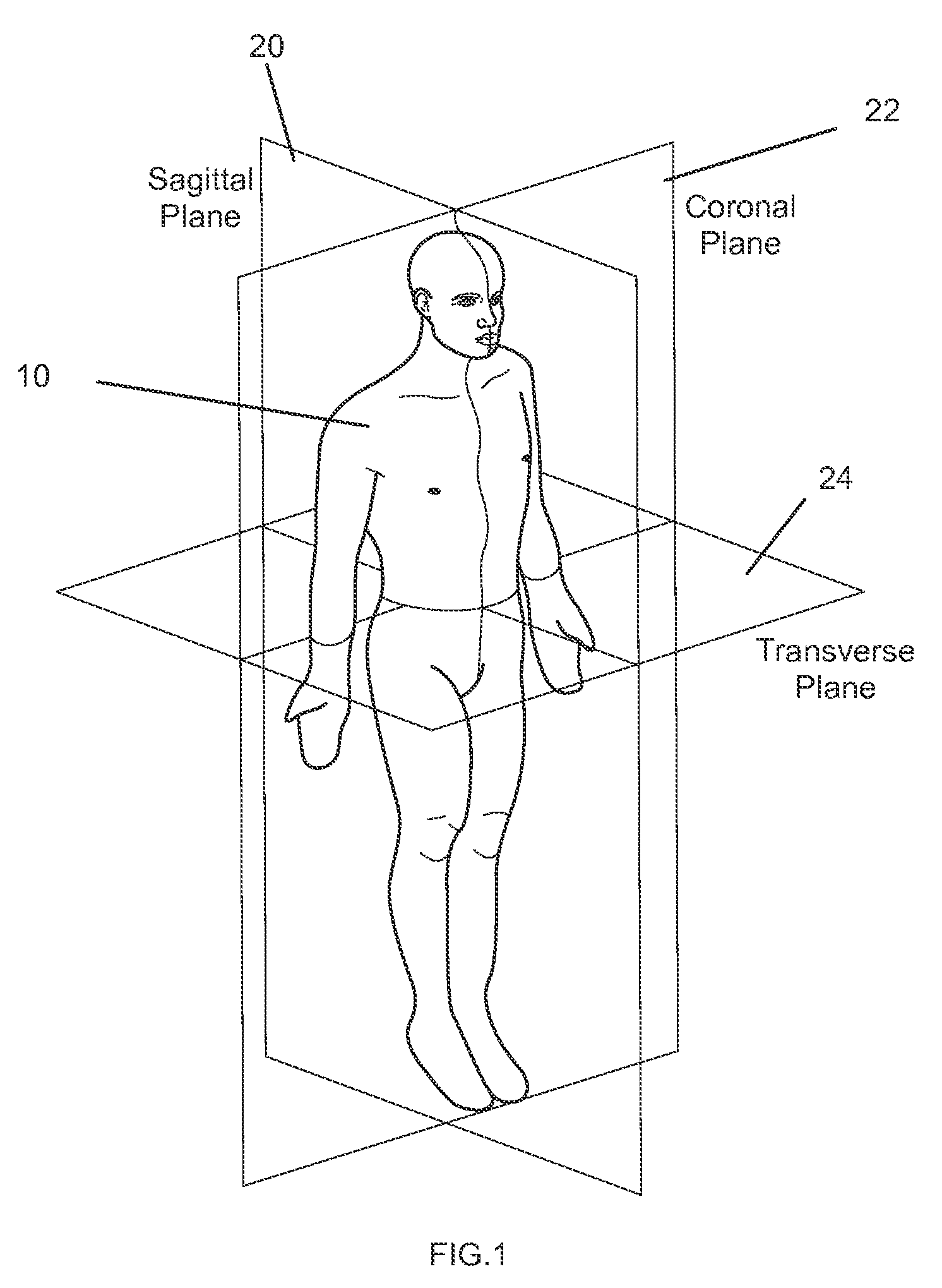
CROSS-REFERENCE TO RELATED APPLICATION[0001]This application is the U.S. National Phase under 35 U.S.C. 371 of International Application No. PCT / US2011 / 031267, filed on Apr. 5, 2011, which claims the benefit of U.S. Provisional Patent Application No. 61 / 321,250, filed Apr. 6, 2010. The entire contents of these applications are herein incorporated by reference.BACKGROUND[0002]1. Field[0003]The present disclosure generally relates to systems and methods for correcting spinal deformities.[0004]2. Description of the Related Art[0005]The treatment of spinal deformity requires a three dimensional approach and therefore is organized into three primary planes of correction relative to the human body. These three planes include the frontal or coronal plane, the sagittal or lateral plane, and the transverse or axial plane as shown in FIG. 1. Correction and proper alignment of these three planes is often the goal of the surgeon in the treatment of spinal deformity. Spinal deformities of varyin...

Claims


Application Information

Patent Timeline
Patent Type & Authority Patents(United States)
IPC IPC(8): A61B17/70A61B17/86A61B19/00
CPCA61B17/70A61B17/708A61B17/7011A61B17/7032A61B17/7038A61B17/8605A61B17/7037A61B2019/307A61B2019/446A61B2019/461A61B90/94A61B2090/037A61B2090/061A61B17/7035A61B17/7083A61B17/8615A61B17/8665A61B17/8685
Inventor DI LAURO, MICHAELCORDARO, NICHOLAS M.WOO, RAYMUNDMATHIOS, DEVIN
Owner SEASPINE
Why Eureka
Try Eureka