Haptic device capable of managing distributed force

a technology of distributed force and tactile devices, applied in the field of tactile devices, can solve the problem that the mechanism enforces a practical limit as to the distance between the devices from one another

Active Publication Date: 2015-09-22
CROFFORD JONATHAN M
View PDF46 Cites 14 Cited by
  • Summary
  • Abstract
  • Description
  • Claims
  • Application Information

AI Technical Summary

Benefits of technology

[0008]Embodiments of the invention may be implemented by way of a motorized device, having a structural support for a plurality of pins. The distal ends of the pins define a surface from which the pins can extend. The device includes motors that are selectably coupled to the pins by way of one or more actuators. The motors operate to extend or retract the pins, or to hold the pins in place, under the control of the actuators. The actuators are coupled to a processor. In some embodiments, the processor issues signals to the actuators to extend, retract, or hold the pins. In other embodiments, the processor receives a signal from the actuators corresponding to external pressure applied against the pins.

Problems solved by technology

However, this shared motor mechanism necessarily enforces a practical limit as to how remote the devices can be from one another, and as to the response of the devices to one another.

Method used


Image

  • Haptic device capable of managing distributed force
  • Haptic device capable of managing distributed force
  • Haptic device capable of managing distributed force

Examples


Embodiment Construction

[0031]This invention will be described in connection with various ones of its embodiments. It is to be understood that those embodiments and the remainder of the following description are provided by way of example only, and are not intended to limit the true scope of this invention as claimed.

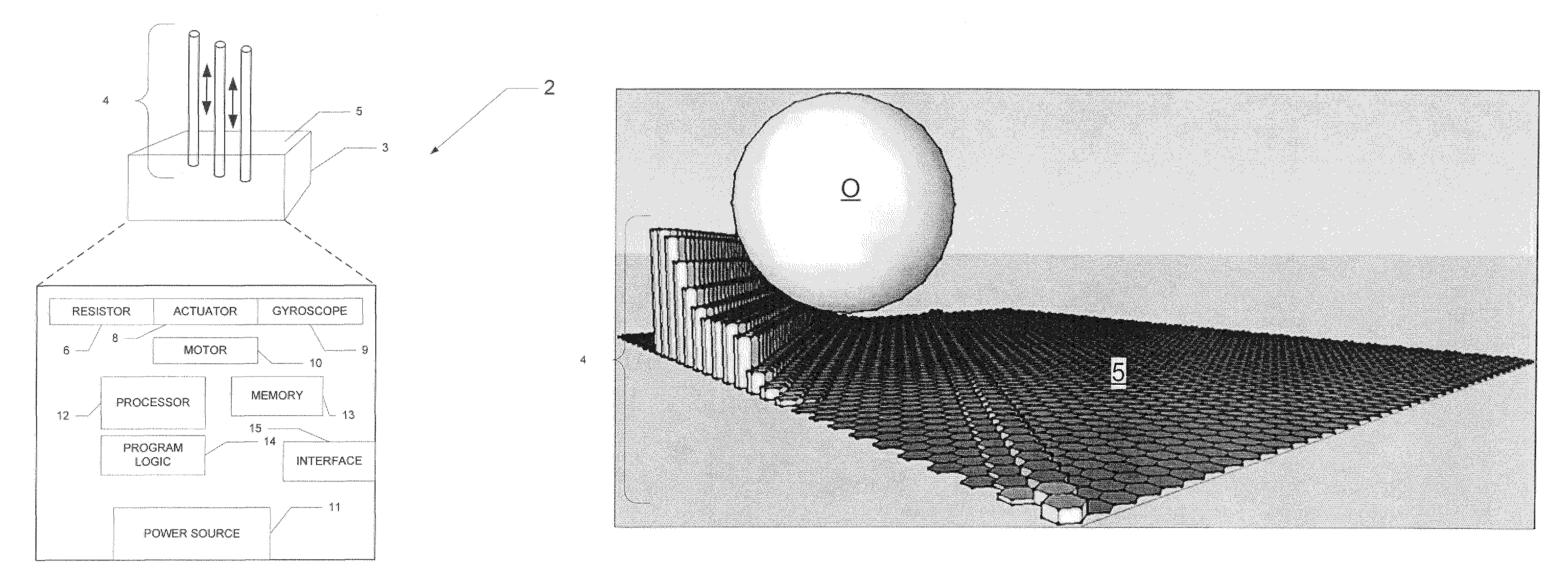
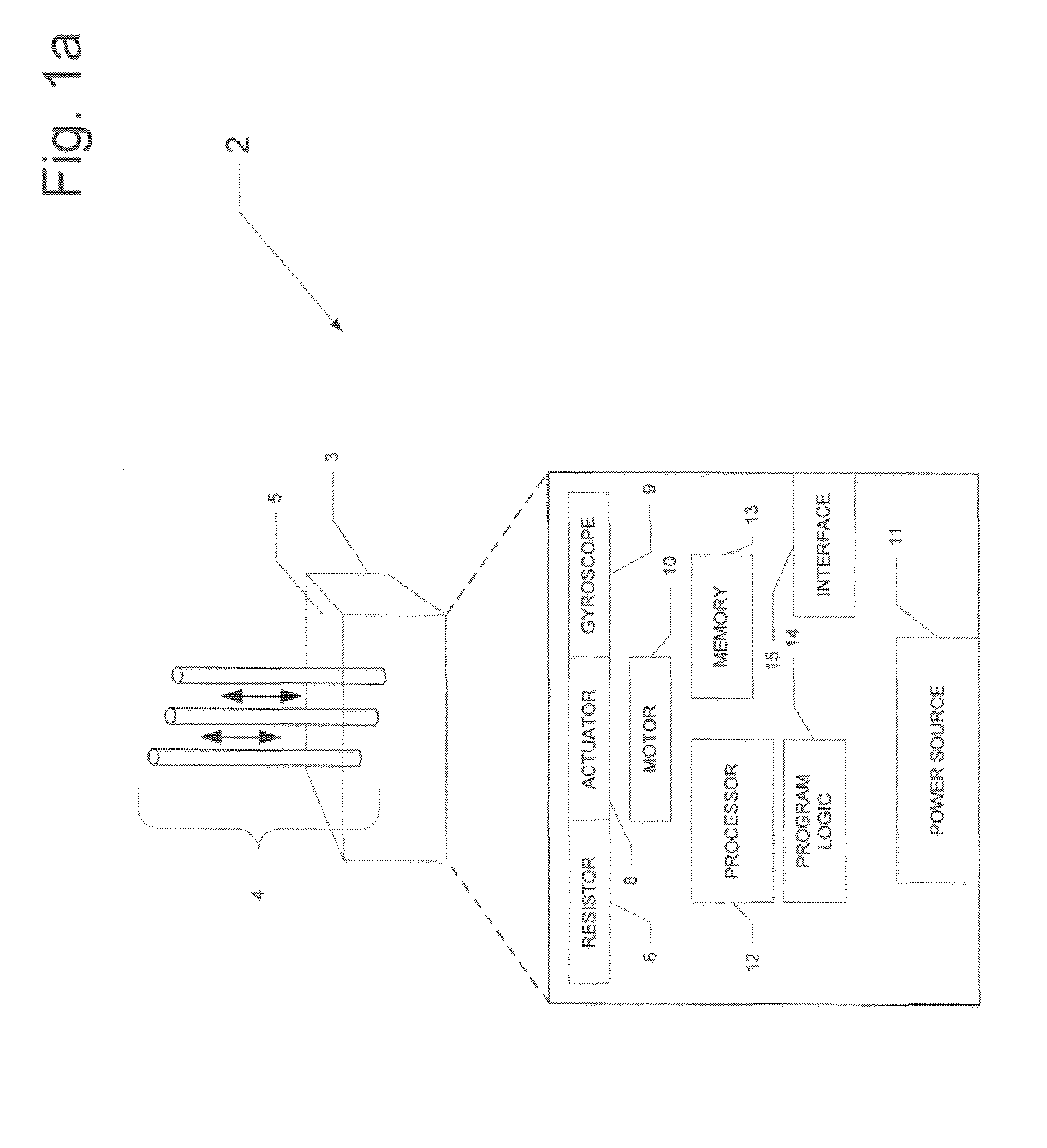
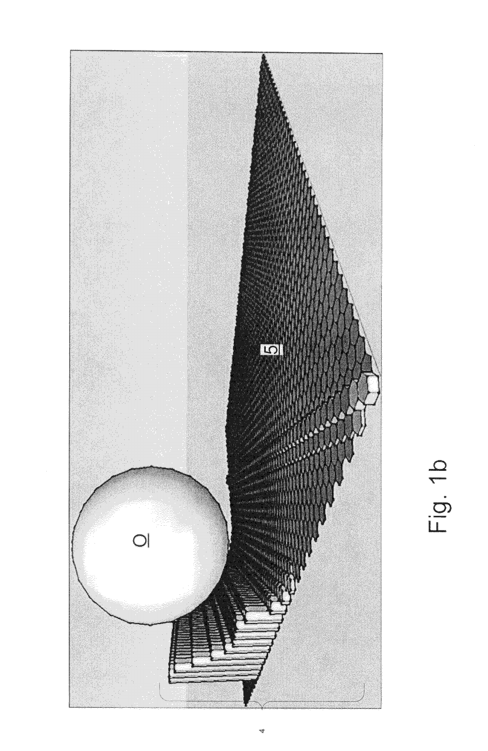
[0032]FIG. 1a illustrates, in functional block diagram form, the construction of haptic device 2 according to embodiments of the invention. In a general sense, enclosure 3 supports multiple pins 4, each of which is movable along its axis as suggested by the arrows in FIG. 1a. According to embodiments of this invention, the distal surfaces of pins 4 defines a surface, which is typically planar with all pins 4 retracted to a nominal position, and from which one or more of pins 4 can extend. Three pins 4 are shown in FIG. 1a for the sake of clarity but, as will be described below, it is contemplated that the number of pins 4 typically used will be in the tens or hundreds, with pins 4 typically ar...


PUM


Abstract

A haptic device operated alone or interacts with other physical or virtual devices of similar design that enable users to remotely image, analyze, or manipulate objects, either manually and or with the assistance of computer programs. The device extends and retracts “pins” in reaction to messages from a processor, and to external pressure applied to the pins' topical surface. A support structure provides a constant geometric plane. An operating system is provided that is capable of interaction for any one of a collection of devices of varying size and function. Multiple devices that are paired or otherwise positioned relative to one another, or scaled in size relative to one another, can be controlled to operate in cooperation with one another.

Description

CROSS-REFERENCE TO RELATED APPLICATIONS[0001]This application claims priority, under 35 U.S.C. §119(e), of Provisional Application No. 61 / 654,305, filed Jun. 1, 2012, and incorporated herein by this reference.STATEMENT REGARDING FEDERALLY SPONSORED RESEARCH OR DEVELOPMENT[0002]Not applicable.BACKGROUND OF THE INVENTION[0003]This invention is in the field of haptic devices. Embodiments of the invention are more specifically directed to remote force management by operation of one or more haptic devices.[0004]Conventional computer systems typically interface with their users, and with the “outside world” in general, by way of graphics and text. Even pointing devices (e.g., mouse, trackball, trackpad) operate in a graphical sense, by navigating a cursor among graphical elements. In the industrial context, additional interface approaches include the receiving of inputs from sensors and transducers, and the outputting of motor control signals in either of the digital and analog domains.[0...

Claims


Application Information

Patent Timeline
Patent Type & Authority Patents(United States)
IPC IPC(8): H04B3/36G08B6/00
CPCG08B6/00G06F3/016
Inventor CROFFORD, JONATHAN M.
Owner CROFFORD JONATHAN M
Why Eureka
Try Eureka