Method and apparatus for joining screen material for minimal optical distortion

A bonding material and minimization technology, applied in optics, thin material handling, transportation and packaging, etc.

Inactive Publication Date: 2014-05-07
REAID INC
View PDF4 Cites 3 Cited by
  • Summary
  • Abstract
  • Description
  • Claims
  • Application Information

AI Technical Summary

Problems solved by technology

There are several acceptable joining methods for PVC screens, each with process-specific challenges

Method used


Image

  • Method and apparatus for joining screen material for minimal optical distortion
  • Method and apparatus for joining screen material for minimal optical distortion
  • Method and apparatus for joining screen material for minimal optical distortion

Examples


Embodiment Construction

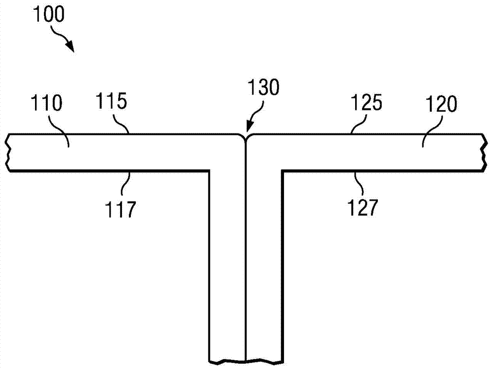
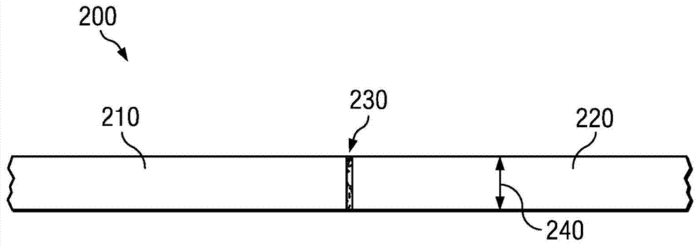
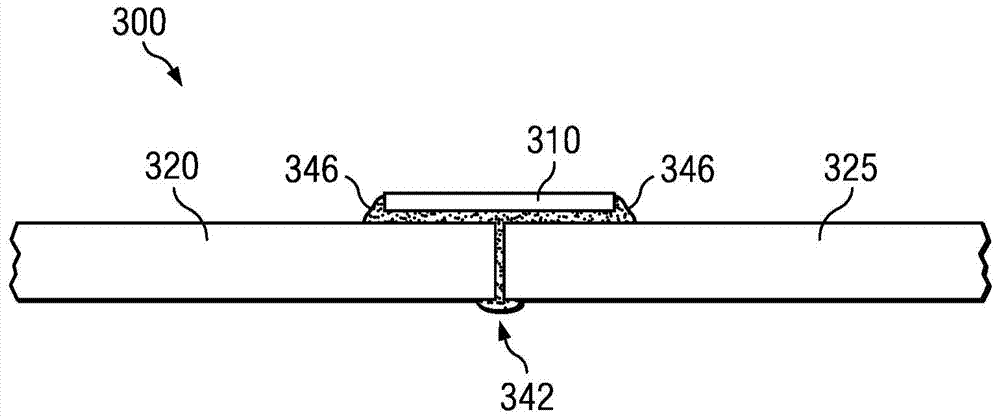
[0015] According to the present disclosure, a method for joining materials may include positioning a first edge of a first piece of material adjacent to a first edge of a second piece of material to create a seam, and positioning a first side of a third piece of material adjacent to The seam, wherein the optical impact of changes in local surface normals in the vicinity of the seam is substantially minimized. The first and second pieces of material may be substrates whose first side is covered with an optically functional material and may be substrates with a relatively high tensile modulus. The third piece of material may be adjacent to the seam and may be adhered to the seam by using an adhesive such as PSA, which may be a curable adhesive and in one embodiment, May be cured using UV radiation. Furthermore, a third piece of material may be adhered to the first and second pieces of material on a second side opposite to said first side covered with optically functional materi...


PUM


Abstract

The present disclosure describes a manufacturing method for seaming materials. The process may be suitable for manufacturing high performance projection screens using a number of methods including, but not limited to, conventional (convert-before-coating) methods, or convert-after-coating methods. An objective of the present disclosure is to identify a process which may substantially minimize distortion of the local surface normal in the vicinity of the join.

Description

[0001] Cross References to Related Applications : This application requires submission on July 13, 2011, entitled "Method and apparatus for joining screen material for minimal optical distortion (Method and apparatus for joining screen material for minimal optical distortion)", serial number No.61 / 507,574, which is hereby incorporated by reference in its entirety. technical field [0002] The present disclosure relates generally to bonding materials, and more particularly, to bonding screen materials, such as front projection screens, including polarization maintaining front projection screens. Background technique [0003] Generally, the front projection screen of a theater is made of a low-modulus substrate, such as plasticized polyvinyl chloride (PVC), with a thickness of about 300 microns. One of the benefits of such a substrate is that when the material is placed under a tensile load, variations affecting the local surface normal (which may affect screen appearance) a...

Claims


Application Information

Patent Timeline
Patent Type & Authority Applications(China)
IPC IPC(8): G03B21/56
CPCG03B21/56Y10T156/1089Y10T428/24752
Inventor G·D·夏普D·A·科尔曼D·K·康多
Owner REAID INC
Why Eureka
Try Eureka