
Motor driving control apparatus

a technology of motor driving and control apparatus, which is applied in the direction of electric motor control, electronic commutation motor control, transportation and packaging, etc., can solve the problems of linearity, linearity, and efficiency sacrifice, and the linearity of torque control is greatly worsened

Active Publication Date: 2015-10-20
MICROSPACE +1
View PDF41 Cites 8 Cited by
  • Summary
  • Abstract
  • Description
  • Claims
  • Application Information

AI Technical Summary

Benefits of technology

[0018]Also, the motor drive control apparatus relating to the first mode may further include a calibrating unit that calibrates the fourth value so as to reduce a drive current of the motor according to a deviation of a fifth value that is obtained by converting a sixth value corresponding to the drive current into toque, when the fifth value deviates from the fourth value by a predetermined permissible amount or more. Thus, this motor drive control apparatus is secure, because the fourth value (i.e. the target torque) is calibrated to reduce the drive current of the motor even in such cases where the drive current of the motor is increasing for some reason, or is detected to be increasing.
[0039]Also, the motor drive control apparatus relating to the second mode has (A) a speed processing unit that generates a first value by converting a second value corresponding to a current speed into a duty ratio; (B) a torque processing unit that generates a third value by converting a fourth value corresponding to a target torque into the duty ratio; (C) a drive unit that controls switching by a switch included in a complementary switching amplifier by an average duty ratio corresponding to a sum of the first value and the third value to drive a motor connected to the complementary switching amplifier; and (D) a calibrating unit that calibrates a second duty ratio conversion coefficient in the torque processing unit based on a reference value of a first duty ratio conversion coefficient in the speed processing unit, a value of the first duty ratio conversion coefficient, which is calibrated so that a motor drive current becomes zero when the fourth value is zero, and a reference value of the second duty ratio conversion coefficient. As a result, the torque processing unit can perform a processing using a suitably calibrated coefficient value.

Problems solved by technology

However, efficiency is sacrificed due the drop voltage of the diode.
Because the counter-electromotive force is in proportion to the sinusoidal voltage output when compared to the motor rotation speed, the applied voltage is not proportional to the current and therefore also the torque, this causes a problem in which the linearity of torque control greatly worsens, and this linearity is also largely affected by the speed.
For this reason, in order to obtain the target torque, an extremely complicated correction control regarding the speed and target torque is necessary.
Although accuracy is high due to a control that monitors the current, which is the control result, the disadvantage is that negative return control can easily cause instability, and so to create a stable feedback control, a control which is a sufficiently low cut-off frequency is requested regarding a loop response (motor current detection→microcomputer calculation→output instruction), which slows the response making it necessary to further increase the speed and accuracy of the loop response.
Also, if there is a break up in the information indicating where the return should occur, this could cause a problem where the control amount is determined to be insufficient, and so excessive response attempts are made.
In the case of this control system, the integrator causes phase lag in the high-frequency region, and so there is a possibility that a lag element in the motor, which is the control object, causes oscillation.
However, when complicating the control system in this way, it is necessary to model the inverter and motor that are the control subjects, which may cause a change in properties due to modeling errors or variance and degradation of devices developed from models without errors and therefore possibly cause oscillation.

Method used


Image

  • Motor driving control apparatus
  • Motor driving control apparatus
  • Motor driving control apparatus

Examples


first embodiment

[First Embodiment]

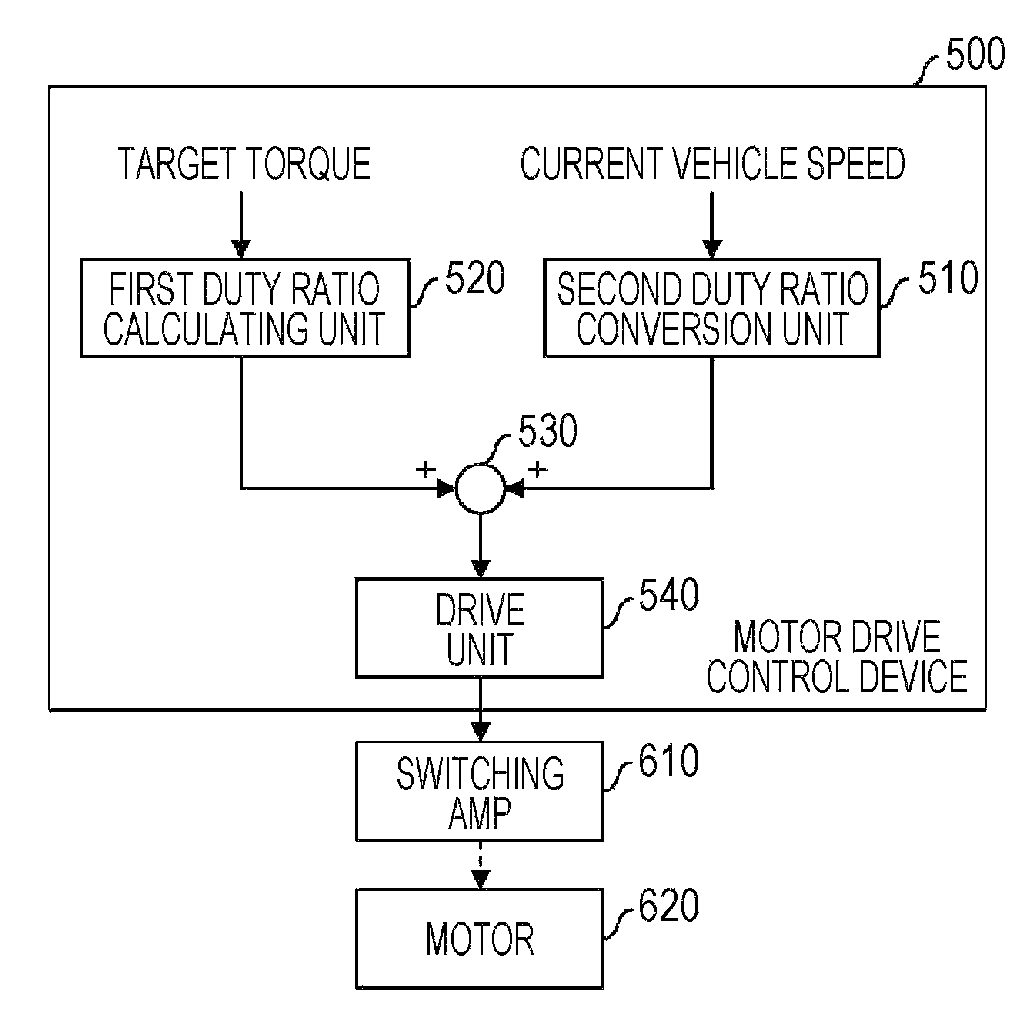
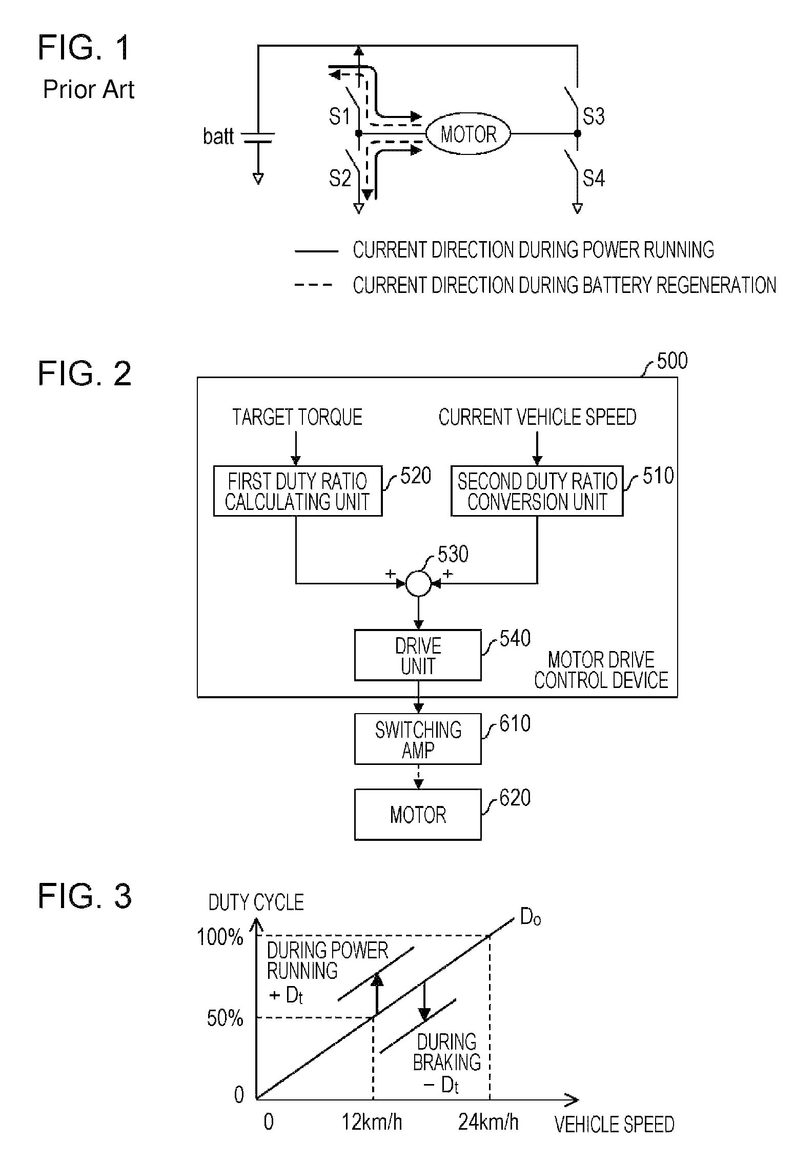
[0072]FIG. 2 is a functional block diagram of a motor drive control device 500 related to the present embodiment. The motor drive control device 500 includes a first duty cycle conversion unit 520, a second duty cycle conversion unit 510, an adding unit 530, and a drive unit 540. The output of the drive unit 540 of the motor drive control device 500 is connected to a complementary type switching amplifier 610, and a motor 620 is driven by this switching amplifier 610.

[0073]For example, a first digital value corresponding to the current speed from a sensor connected to the applicable the motor drive control device 500 and a third digital value corresponding to a target torque from an instruction mechanism or sensor connected to the motor drive control device 500 is input into the motor drive control device 500, and so processing is performed there. Also, the second duty cycle conversion unit 510 executes processing to multiply the conversion coefficient with the fir...

second embodiment

[Second Embodiment]

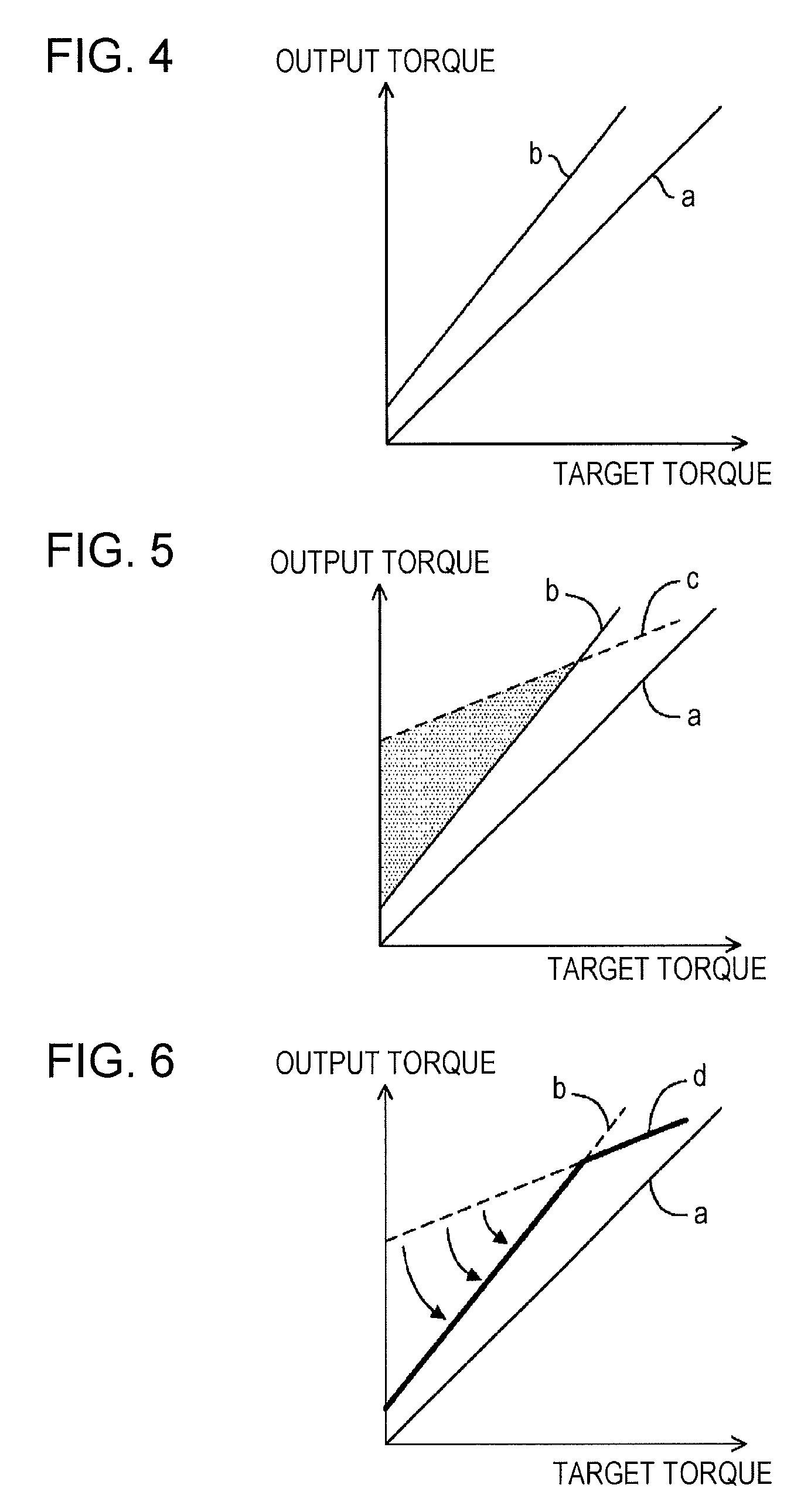
[0080]Regarding the first Embodiment, there is no problem when obtaining the output torque corresponding to the target torque, but current flowing to the motor could increase due to variances in components and such, and as a result, this can cause a torque larger than the target torque to be produced.

[0081]As illustrated in FIG. 4, it is generally preferable if the output torque corresponding to the target torque matches as illustrated by the straight line a. Also, for safety reasons, the output torque should be set corresponding to the target torque, and also should be set to a value in the region below the upper limit of the allowable amount as illustrated by the straight line b. However, as indicated by the dotted line c illustrated in FIG. 5, if the current flowing to the motor is increased for some reason, a larger current than that corresponding to the target torque flows, and as a result, there may be cases in which an output torque in a region (shaded area...

third embodiment

[Third Embodiment]

[0095]The third Embodiment of the present invention will be described using FIG. 8 through FIG. 27. Here, this will be described using an example of a so-called electrically assisted bicycle in which the motor is installed on a bicycle.

[0096]FIG. 8 is an external view illustrating an example of an electrically assisted bicycle related to the third Embodiment. The electrically assisted bicycle 1 is typical rear wheel drive type with a crankshaft and a rear wheel connected by a chain, and has a motor drive device installed. The motor drive device includes a secondary battery 101, a motor drive control mechanism 102, a torque sensor 103, a brake sensor 104, a motor 105, and an operation panel 106.

[0097]The secondary battery 101 may be, for example, a lithium ion secondary battery with a maximum supply voltage of 24 V (when fully charged), but other types of batteries such as a lithium ion polymer secondary battery, or a nickel hydride chargeable battery may be used.

[0...


PUM


Abstract

A motor drive control apparatus for performing motor control that is stable and has a good efficiency includes: a speed processing unit that generates a first value by converting a second value corresponding to a current speed into a duty ratio; a torque processing unit that generates a third value by converting a fourth value corresponding to a target torque into the duty ratio; and a drive unit that controls switching by a switch included in a complementary switching amplifier by an average duty ratio corresponding to a sum of the first value and the third value to drive a motor connected to the complementary switching amplifier.

Description

CROSS-REFERENCE TO RELATED APPLICATIONS[0001]This application is a U.S. national stage application of PCT / JP2011 / 078761 filed Dec. 13, 2011 and claims foreign priority benefit of Japanese Application No. 2010-285553 filed Dec. 22, 2010 and Japanese Application No. 2010-285668 filed Dec. 22, 2010 in the Japanese Intellectual Property Office, the contents of both of which are incorporated herein by reference.TECHNICAL FIELD[0002]The present invention relates to motor driving control.BACKGROUND TECHNOLOGY[0003]FIG. 1 is a diagram illustrating a description of basic operation for a motor driving. The motor driving state is controlled by control of a duty ratio from switching between FET or other switches S1 through S4, which includes this kind of an H bridge circuit. For example, when a large voltage Vout by a counter-electromotive force Vmotor generated by motor rotations is supplied from a battery batt, the motor is in a power running state. When controlling the duty ratio of the swit...

Claims


Application Information

Patent Timeline
Patent Type & Authority Patents(United States)
IPC IPC(8): B62M6/45B60L11/00H02P6/08H02P7/28H02P29/00
CPCB62M6/45B60L11/007H02P6/085H02P7/28Y02T10/642B60L50/20Y02T10/64B62M23/02
Inventor TANAKA, MASATOASANUMA, KAZUOHOSAKA, YASUO
Owner MICROSPACE
Learn More