
Press machine and method of controlling press machine

a press machine and press technology, applied in the direction of control systems, electrical equipment, ac motor control, etc., can solve the problems of abnormal stop of the press machine, high load could act on the servo motor, and the servo amplifier is inevitably overheated, so as to reduce the drive current of the servo motor and reduce the press production speed

Inactive Publication Date: 2018-12-11
KOMATSU IND CORP
View PDF16 Cites 0 Cited by
  • Summary
  • Abstract
  • Description
  • Claims
  • Application Information

AI Technical Summary

Benefits of technology

Enables continuous production by reducing drive current and preventing overheating, while providing visual and operational feedback to manage production speed effectively.

Problems solved by technology

However, in some settings, a high load could act on the servo motor.
When the press machine continues to be operated with such a setting being employed, a servo amplifier is inevitably overheated.
This results in abnormal stop of the press machine.
However, when the motor current exceeds the threshold during the press operation, it takes time to stop the press machine and perform a setting work again.

Method used


Image

  • Press machine and method of controlling press machine
  • Press machine and method of controlling press machine
  • Press machine and method of controlling press machine

Examples


Embodiment Construction

[0034]Construction

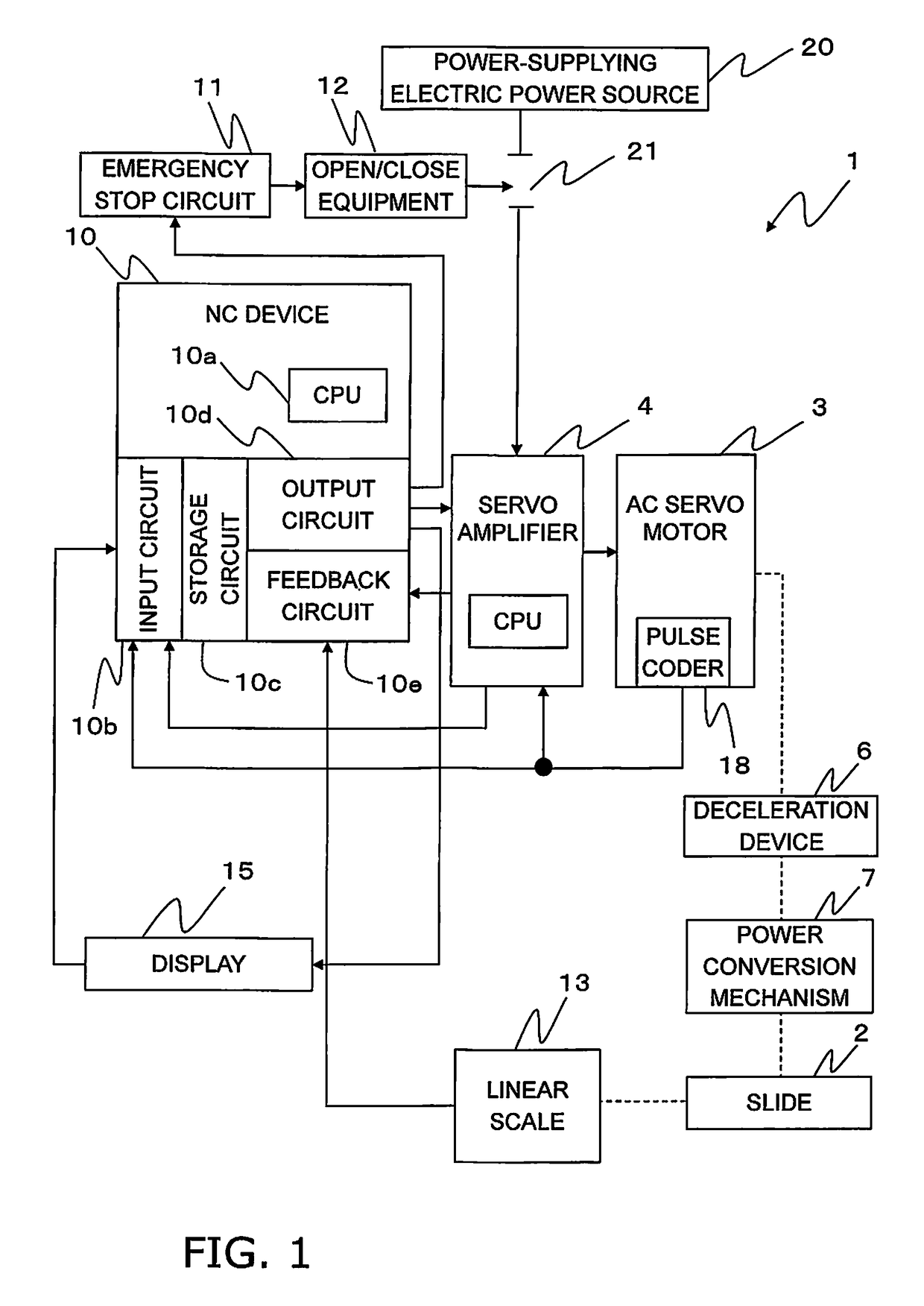
[0035]FIG. 1 is a block diagram of an electric servo press according to an exemplary embodiment of the present invention. The present electric servo press 1 includes a slide 2, an AC servo motor 3 and a servo amplifier 4. A deceleration device 6 and a power conversion mechanism 7, which are widely known, are mounted between the AC servo motor 3 and the slide 2. For example, a drum type, an eccentric type, a link type and so forth have been known as types of the power conversion mechanism 7.

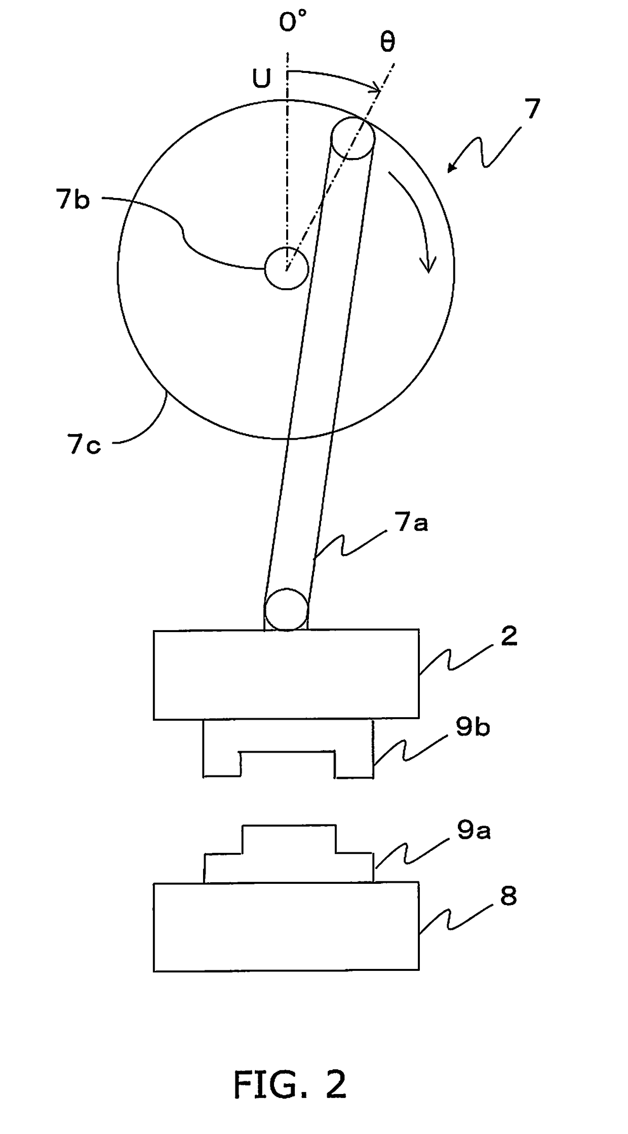
[0036]FIG. 2 is a diagram for explaining an action of the power conversion mechanism 7. In the electric servo press 1, a lower die 9a is fixed onto a bolster 8 installed on a base (not shown in the drawing). An upper die 9b, paired with the lower die 9a, is fixed to the slide 2 over the lower die 9a. The slide 2 is connected to a rotor 7c configured to be rotated about a shaft 7b through an arm 7a. It should be noted that the rotor 7c is schematically illustrated. The slide 2 is ...


PUM


Abstract

A press machine includes a servo amplifier configured to supply a drive current to a servo motor, a current detector for detecting the drive current, a rotational angle detector for detecting a rotational angle of a rotary motion provided by the servo motor, and a controller. The controller is configured to set a press production speed by setting a correspondence between rotational angles and rotational speeds at the rotational angles, which defines the rotary motion. The controller is configured to determine whether or not the drive current detected by the current detector is greater than or equal to a first threshold. The controller is configured to reduce all the rotational speeds by an equal ratio when the drive current detected by the current detector is greater than or equal to the first threshold.

Description

CROSS-REFERENCE TO RELATED APPLICATIONS[0001]This application is a U.S. National stage application of International Application No. PCT / JP2014 / 052513, filed on Feb. 4, 2014. This U.S. National stage application claims priority under 35 U.S.C. § 119(a) to Japanese Patent Application No. 2013-024010, filed in Japan on Feb. 12, 2013, the entire contents of which are hereby incorporated herein by reference.BACKGROUND[0002]Field of the Invention[0003]The present invention relates to a press machine and a method of controlling the press machine, particularly to an electric servo press and a method of controlling the electric servo press.[0004]Background Information[0005]An electric servo press as a type of press machine includes a servo motor, a power conversion mechanism, a slide and so forth. The power conversion mechanism is configured to convert the rotational driving power of the servo motor into the up-and-down reciprocating motion of the slide. Then, stamping of a workpiece is perf...

Claims


Application Information

Patent Timeline
Patent Type & Authority Patents(United States)
IPC IPC(8): B30B15/14H02P29/024H02P25/032H02P29/032H02H7/08B30B1/26B30B15/28
CPCB30B15/148B30B1/266H02H7/08H02P29/027H02P29/032H02P25/032B30B15/281
Inventor YAMADA, YUKIHIRO
Owner KOMATSU IND CORP
Learn More