Retroreflective sheet and fabrication method thereof

a technology of retroreflective sheet and fabrication method, which is applied in the direction of optics, instruments, optical elements, etc., can solve the problems of easy delamination complicated manufacturing process, so as to prevent the formation of light reflective members in the reflective region from being easily delaminated from the body

Active Publication Date: 2015-10-27
HJ
View PDF1 Cites 0 Cited by
  • Summary
  • Abstract
  • Description
  • Claims
  • Application Information

AI Technical Summary

Benefits of technology

[0018]It is, therefore, an object of the present invention to provide a retroreflective sheet for preventing a light reflective member formed in a reflective region from easily being delaminated from the body.
[0019]Another object of the present invention is to provide a method for manufacturing a retroreflective sheet capable of preventing a generation of a step between a reflective region and a non-reflective region due to a light reflective member.
[0020]Still another object of the present invention is to provide a method for manufacturing a retroreflective sheet capable of simply forming a light reflective member on a carrier film without performing a cutting operation.
[0028]In accordance with another aspect of the present invention, there is provided a method for fabricating a retroreflective sheet, including: forming a bead alignment layer on a carrier film and attaching a mask tape in a non-reflective region NRA2 on the bead alignment layer to confine a reflective region RA2 and the non-reflective region NRA2; sprinkling a plurality of beads to the bead alignment layer such that they form a layer to form a light concentrating layer in the reflective region; depositing a metal having excellent light reflecting characteristics on the surface of the mask tape and the light concentrating layer to form a reflective layer; removing the mask tape such that the reflective layer remains on the light concentrating layer and the bead alignment layer of the non-reflective region NRA2 is exposed, and forming a colored layer covering the reflective layer on the exposed bead alignment layer; forming a bonding layer on the colored layer and thermally compressing a base to the bonding layer; and delaminating the carrier film having the bead alignment layer to expose the colored layer and the light concentrating layer.

Problems solved by technology

However, in the foregoing retroreflective sheet according to the prior art, since the light reflective member 23 is formed only in the reflective region, not in the non-reflective region, a step is formed between the reflective region and the non-reflective region, causing a problem in which the light reflective member formed in the reflective region is easily delaminated from the body.
In addition, since the light reflective member together with the carrier film are cut, attached to the base, and then, the carrier film including the bead alignment layer as a light reflective film is delaminated, the manufacturing process is complicated.

Method used


Image

  • Retroreflective sheet and fabrication method thereof
  • Retroreflective sheet and fabrication method thereof
  • Retroreflective sheet and fabrication method thereof

Examples


Embodiment Construction

[0043]Hereinafter, embodiments of the present invention will be described in detail with the accompanying drawings.

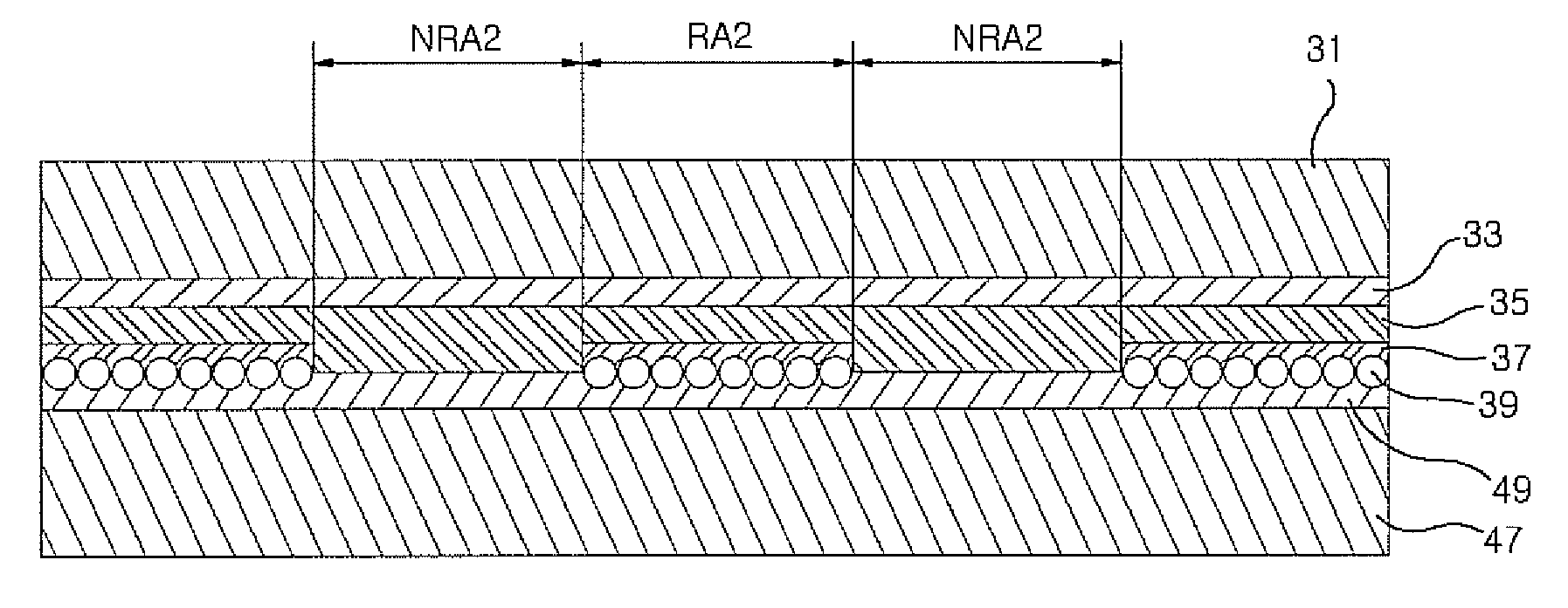
[0044]FIG. 3 is a cross-sectional view of a retroreflective sheet in accordance with an embodiment of the present invention.

[0045]A retroreflective sheet in accordance with the present invention includes a base 31, a bonding layer 33, a colored layer 35, a reflective layer 37, and a light concentrating layer 41, and reflective regions RA2 and non-reflective regions NRA2 are formed to be alternated in a stripe pattern. The reflective layer 37 and the light concentrating layer 41 constitute a light reflective member 45.

[0046]The base 31 is made of flame-retardant all-cotton fiber, glass fiber, aramid fiber, hemp fiber, wool fiber, polyester fiber, cotton blend (TO) fiber, or the like.

[0047]The bonding layer 33 is formed by coating one or a mixture of two or more of adhesive synthetic resins having excellent heat resistance such as polyester, polyurethane, poly ethylene vi...


PUM


Abstract

A retroreflective sheet and a fabrication method thereof are provided, the retroreflective sheet including a base, a bonding layer formed on the base, a colored layer formed to be thicker in a non-reflective region NRA2 than in a reflective region RA2 to have a concavo-convex surface on the bonding layer, and having a fluorescent function or a phosphorescent function or having the both fluorescent and phosphorescent functions, a reflective layer formed in the concave portion of the reflective region RA2 on the surface of the colored layer, and a light concentrating layer having a plurality of beads aligned therein on the reflective layer. Thus, since a step is not generated between the reflective region and the non-reflective region, the light reflective member can be prevented from being delaminated from the body when used, and also, the light reflective member can be simply formed in the reflective region of the colored layer.

Description

CROSS-REFERENCE TO RELATED APPLICATIONS[0001]The present application claims priority of Korean Patent Application No. 10-2012-0079498, filed on Jul. 20, 2012, which is incorporated herein by reference in its entirety.FIELD OF THE INVENTION[0002]The present invention relates to a retroreflective sheet and fabrication method thereof, and more particularly, to a retroreflective sheet that does not have a step between a reflective region and a non-reflective region, and a fabrication method thereof.BACKGROUND OF THE INVENTION[0003]A retroreflective sheet is a reflector that reflects incident light in a direction in which the light is made incident as it is. The retroreflective sheet is processed to have a desired shape and pattern on a body surface in a form of a sheet and attached to a traffic sign or a selected portion of a uniform of a fireman and so on, with an adhesive or through sewing or the like, having enhanced visibility, so as to be easily viewed or recognized even in a dark ...

Claims


Application Information

Patent Timeline
Patent Type & Authority Patents(United States)
IPC IPC(8): G02B5/128
CPCG02B5/128
Inventor YOON, SE WON
Owner HJ
Why Eureka
Try Eureka