Coaxial cable connector with independently actuated engagement of inner and outer conductors

a technology of coaxial cable and inner and outer conductors, which is applied in the direction of coupling devices, two-part coupling devices, electrical equipment, etc., can solve the problems of low contact force and difficulty in correcting soldering techniques

Active Publication Date: 2008-08-28
JOHN MEZZALINGUA ASSOC INC
View PDF99 Cites 28 Cited by
  • Summary
  • Abstract
  • Description
  • Claims
  • Application Information

AI Technical Summary

Benefits of technology

[0007]These are other needs are met by a method of connecting a connector to a segment of coaxial cable, wherein according to an exemplary aspect, the method comprises the steps of: (a) providing a connector that includes an opening and comprises (i) a body that has a first end, a second end and a lumen therebetween, (ii) a clamping element that is disposed within the lumen of the body; and (iii) a collet that has a first end and a second end and that is also disposed within the lumen of the body; (b) inserting a segment of coaxial cable into the connector, wherein the segment of coaxial cable includes an outer conductor and a center conductor, and wherein following the completion of step (b) the outer conductor of the cable segment is at least partially surrounded by the clamping element and the center conductor of the coaxial cable segment is at least partially disposed within the collet; (c) causing the clamping element to engage at least a portion of the outer conductor of the coaxial cable segment (e.g., by applying a first axial force onto the connector in a direction away from the opening of the connector and by substantially simultaneously or non-substantially applying a second axial force onto the connector in a direction toward the opening of the connector); (d) causing the collet to engage at least a portion of the center conductor of the coaxial cable segment (e.g., by applying an axial force onto the connector in a direction toward the opening of the connector); and (e) preventing step (d) from occurring until step (c) is completed.

Problems solved by technology

However, this creates low contact forces between the conductor and the collet, and although that is adequate for low power signal transmissions, it can permit oxidation, which, in turn, can disadvantageously cause intermodulation at certain frequencies and at higher transmission powers.
However, it can be difficult to correctly perform such soldering techniques, especially in a field installation setting.

Method used


Image

  • Coaxial cable connector with independently actuated engagement of inner and outer conductors
  • Coaxial cable connector with independently actuated engagement of inner and outer conductors
  • Coaxial cable connector with independently actuated engagement of inner and outer conductors

Examples


Embodiment Construction

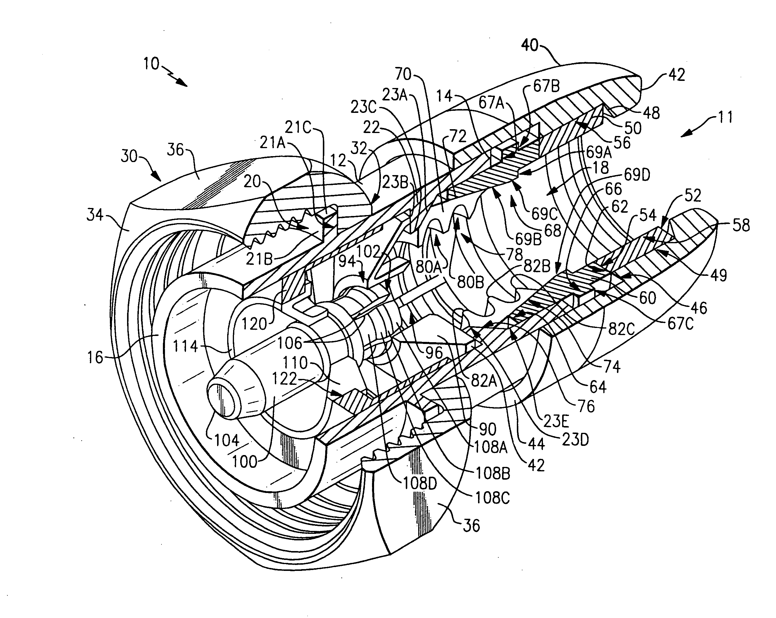
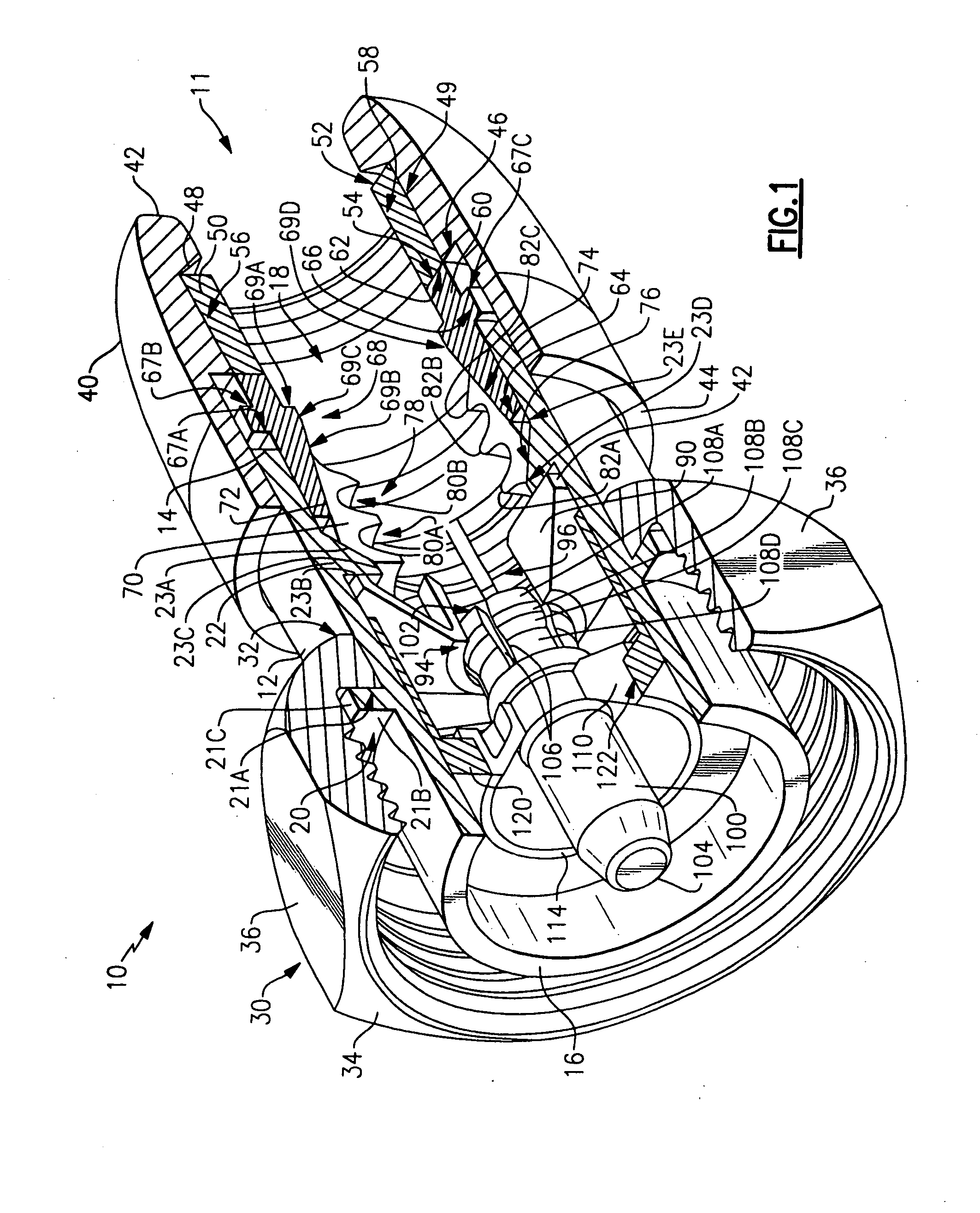
[0030]Referring initially to FIGS. 1-4, an exemplary embodiment of a compression connector 10 for a segment of spiral corrugated coaxial cable 200 (see FIGS. 2-4) is illustrated. The connector 10 includes a substantially cylindrical connector body 12, which has a first end 14, a second end 16, and a continuous lumen 18 defined therebetween. The connector 11 also includes an opening 11 into which the cable segment 200 is inserted as described in further detail below. It is understood that the terms “first end” and “second end” are used herein to refer to opposite ends of an element or object, wherein the “first end” is positioned closer to the opening 11 of the connector 10 than the “second end.”

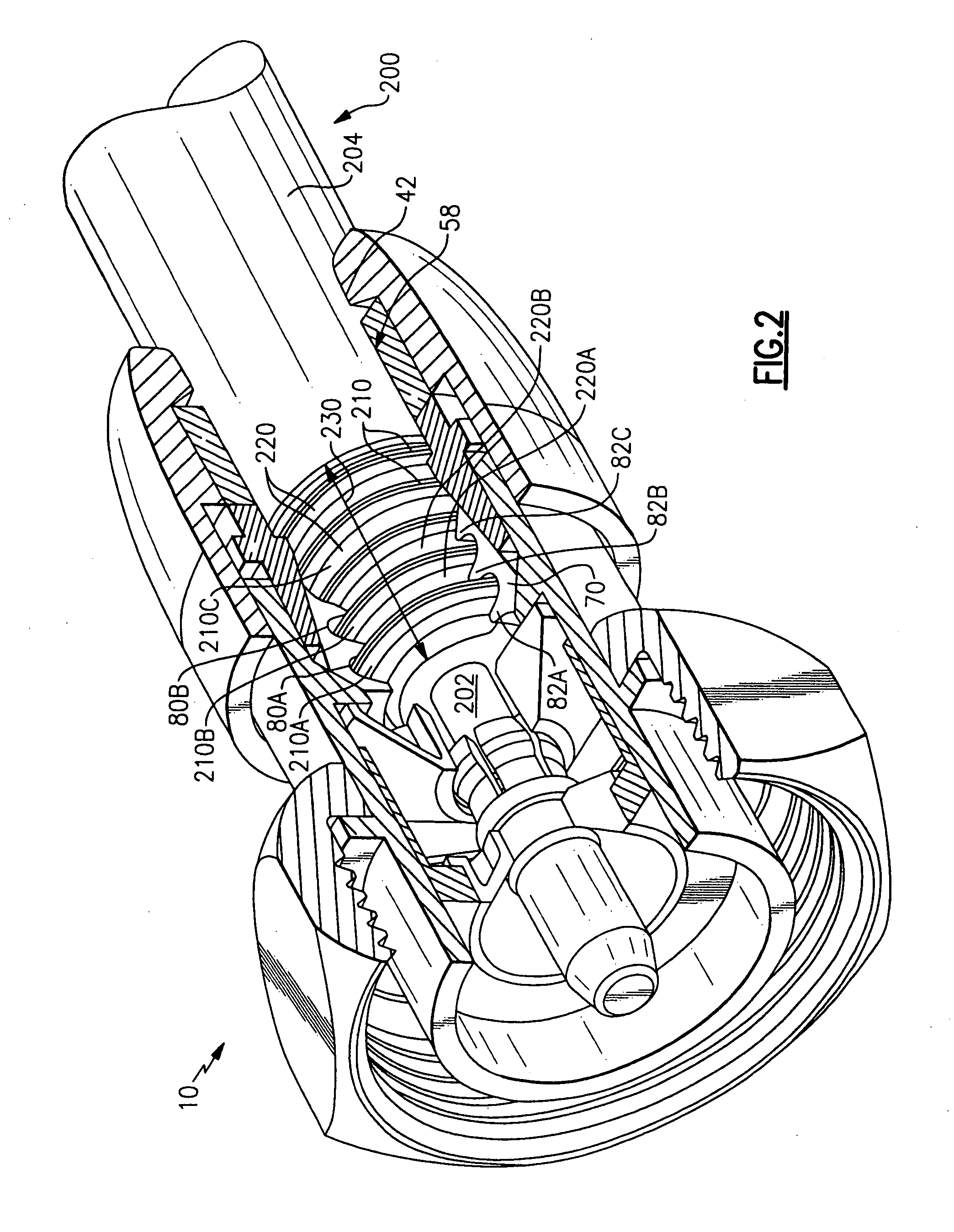
[0031]The cable segment 200 includes a protruding center conductor 202, an outer protective jacket 204, and exposed conductive corrugations shaped to define a plurality of peaks 210 and valleys 220. The peaks 210 and valleys 220 collectively form what is hereinafter referred to as the “expose...


PUM


Abstract

A connector for the end of a segment of coaxial cable is provided wherein the compression connector includes a clamp that is engageable to the outer conductor of the segment of coaxial cable and a collet that can seize the center conductor of the cable, wherein the engagement of the outer conductor and the seizure of the center conductor can occur as separate steps and the center conductor can be prevented from being seized until after the outer conductor has been engaged.

Description

FIELD OF THE INVENTION[0001]The present invention relates generally to coaxial cable connectors, and, more particularly, to a connector for engaging, in separate steps, first the outer conductor and then the center conductor of a segment of coaxial cable.BACKGROUND OF THE INVENTION [0002]Coaxial cable is a typical transmission medium that is used in various modern communications networks, such as CATV networks. At present, installation techniques for coaxial cable can differ depending on various factors, such as the impedance of the cable.[0003]During installation of 75 ohm coaxial cable for example, it is common for a connector to form a positive locking engagement with the center conductor of the cable at the same time as it engages the outer conductor of the cable. Conversely, it is rare for 50 ohm coaxial cable connectors to utilize any positive or locking engagement for the center conductor of the cable. This is because 50 ohm coaxial cable tends not to be a stoutly constructed...

Claims


Application Information

Patent Timeline
Patent Type & Authority Applications(United States)
IPC IPC(8): H01R9/05
CPCH01R9/0521H01R24/564H01R2103/00
Inventor MONTENA, NOAH
Owner JOHN MEZZALINGUA ASSOC INC
Why Eureka
Try Eureka