
Saddle coupling and saddle base assembly for use with power hand tools

a technology of saddle coupling and saddle base, which is applied in the direction of special foundation layout, stand/trestle, machine frame, etc., can solve the problems of repetitive overhead drilling, dangerous overextend of workers, and repetitive use and repositioning of drills, and achieve quick and easy capabilities

Inactive Publication Date: 2015-11-03
BUCHNER DAVID
View PDF37 Cites 6 Cited by
  • Summary
  • Abstract
  • Description
  • Claims
  • Application Information

AI Technical Summary

Benefits of technology

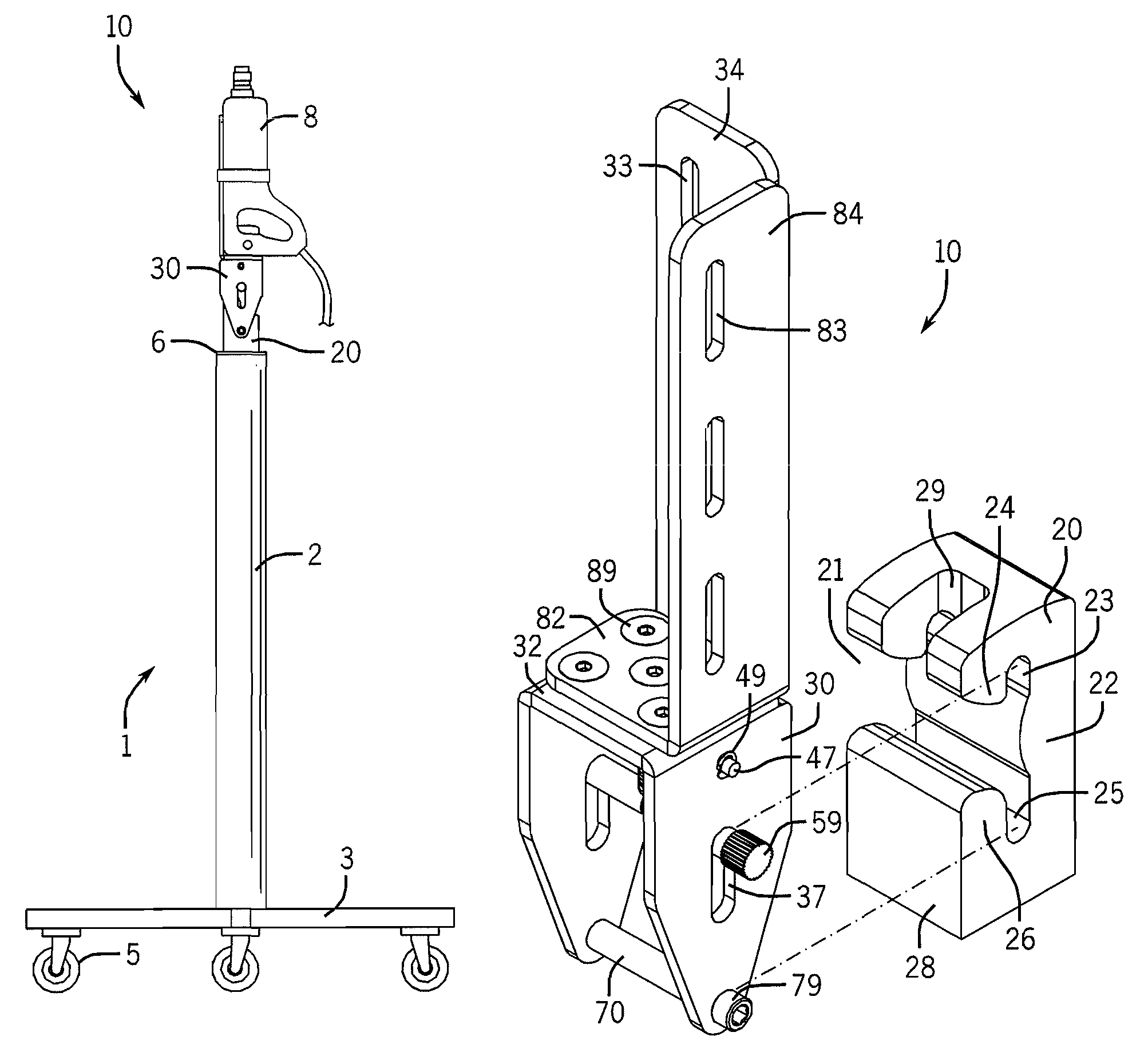
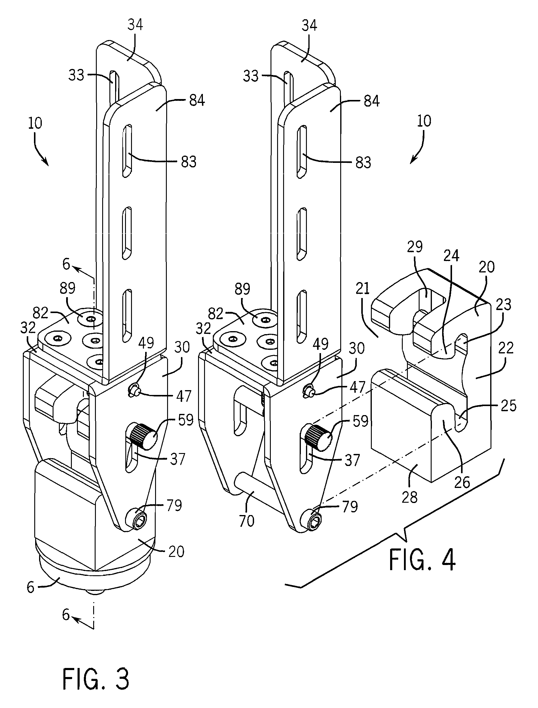
[0007]The present invention is a saddle coupling and saddle base assembly for use with power hand tools. The assembly is mounted to the top of a variably-adjustable stand for drilling holes or inserting fasteners in concrete ceilings or other overhead surfaces. The assembly comprises a saddle base and a saddle coupling that is removably attachable to the saddle base. A plurality of like-configured saddle couplings can be attached to different power hand tools, providing the user with quick and easy capabilities for removing one saddle coupling and power hand tool for another. A single saddle coupling could also allow the user to use the single coupling with a plurality of power hand tools. A spring-loaded locking feature is included in the assembly of the present invention. This is a primary securement means of the assembly. A secondary securement means is also provided in the event of a failure of the primary means.

Problems solved by technology

This means repetitive use and repositioning of the drill by the user.
This repetitive overhead drilling creates a great deal of physical strain for a worker because, not only must the worker support the weight of the drill, but the worker must apply upwardly drilling force as well.
A fundamental problem with this type of work is reaching the overhead surface in the first place.
For taller ceilings, a ladder may not reach or, because obstacles may not be able to be placed directly under the surface to be drilled or close enough to the drilling surface, the worker must dangerously overextend to drill the holes.
The height adjustment and locking mechanism taught by Hurt '724 is not desirable because it is cumbersome to use.
Further, the drill stand of Hurt '724 does not use, teach or suggest the use of a structure that can be used to quickly and easily remove the power hand tool from atop the stand such that a second power hand tool can replace the first.

Method used


Image

  • Saddle coupling and saddle base assembly for use with power hand tools
  • Saddle coupling and saddle base assembly for use with power hand tools
  • Saddle coupling and saddle base assembly for use with power hand tools

Examples


Embodiment Construction

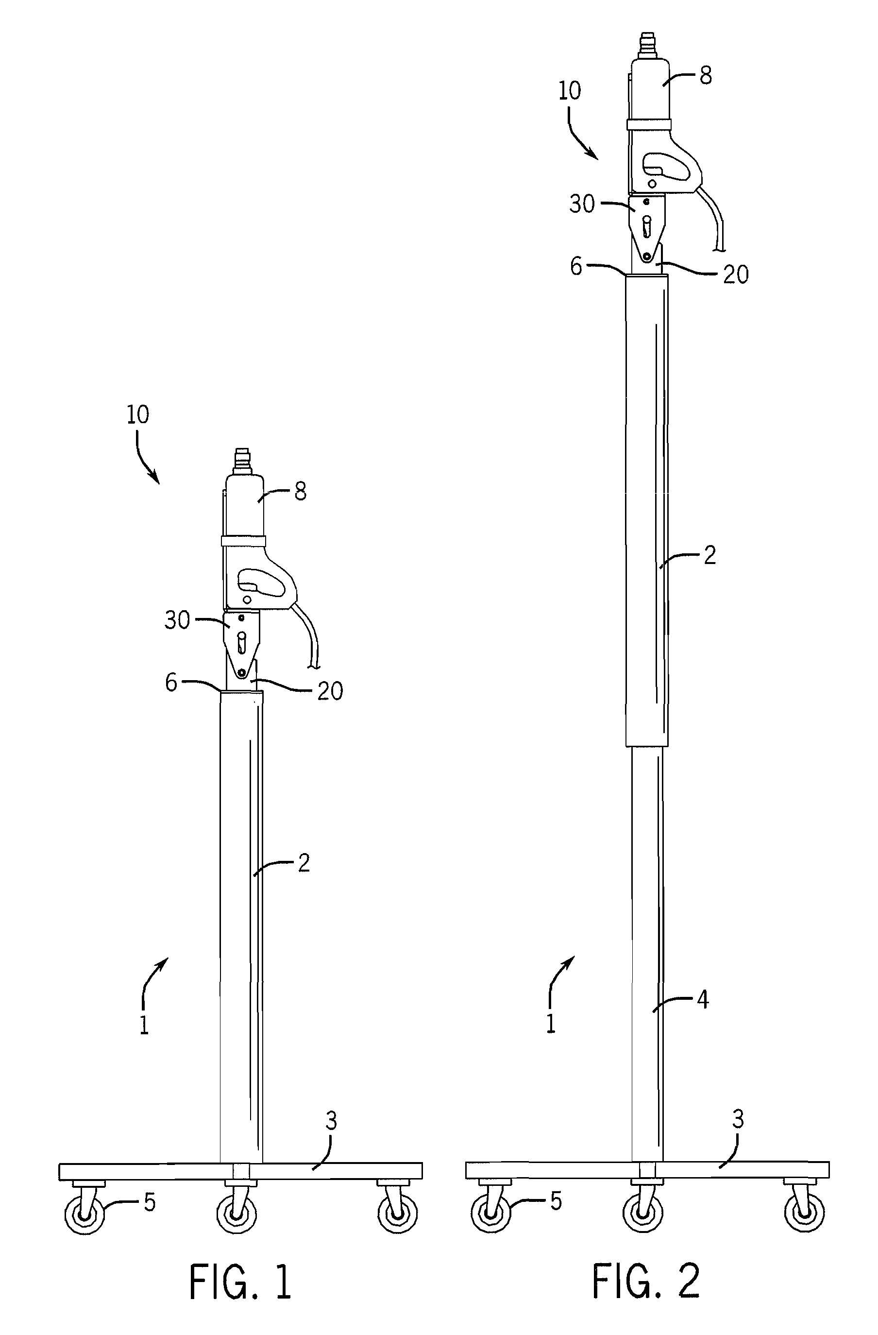
[0019]Referring now to the drawings in detail, wherein like numbered elements refer to like elements throughout, FIGS. 1 and 2 illustrate side elevational views of an exemplary embodiment of the saddle coupling and saddle base assembly, generally identified 10, that is constructed in accordance with the present invention. The assembly 10 is configured to be mounted atop a movable stand 1. The stand 1 comprises a first vertically-disposed tubular section 2 that is attached to a base 3, the base comprising wheels or casters 5 which allow for movement of the stand 1 about a work area having a ceiling surface (not shown). The first tubular section 2 is vertically movable relative to the base 3 and a second tubular section 4. It is to be understood that the precise configuration of the stand 1 is not a limitation of the present invention. For example, the stand 1 could comprise the like structure numbered 100 in applicant's co-pending application, U.S. Pub. No. US 2011 / 0255929 titled Uni...


PUM


Abstract

A saddle coupling and saddle base assembly is provided for use with power hand tools. The assembly is mounted atop a variably-adjustable stand for drilling holes or inserting fasteners into concrete ceilings, drywall ceilings or other overhead surfaces. The assembly comprises a saddle base and a saddle coupling that is removably attachable to the saddle base. The saddle coupling is configured to attach a single power hand tool or a plurality of power hand tools to the coupling. A plurality of like-configured saddle couplings can be attached to different power hand tools to allow the user to quickly and easily remove one saddle coupling and power hand tool and replace it for another. A spring-loaded locking feature is included in the assembly as a primary securement means for the assembly. A secondary securement means is also provided in the event of a failure of the primary means.

Description

FIELD OF THE INVENTION[0001]The present invention relates generally to power hand tools of the type that are used for drilling or cutting into surfaces. More specifically, the present invention relates to a power hand tool saddle coupling and saddle base assembly that can be used with a movable stand for supporting and variably elevating at least one power hand tool proximate to an overhead surface for drilling, nailing or cutting into such surface.BACKGROUND OF THE INVENTION[0002]There are many applications where it is necessary to drill, nail or cut into an overhead surface, such as a concrete ceiling or a drywall ceiling. Such overhead surfaces can vary in their height from the floor. For example, before installing fasteners into concrete ceilings for overhead surfaces, it is usually necessary to first drill holes. Such holes are typically drilled using a hand-held power drill. In most applications, many such holes must be drilled within a single area. This means repetitive use a...

Claims


Application Information

Patent Timeline
Patent Type & Authority Patents(United States)
IPC IPC(8): F16M1/00F16M9/00F16M11/00B25H1/00F16M7/00F16M5/00F16M3/00
CPCB25H1/0035
Inventor BUCHNER, DAVID
Owner BUCHNER DAVID
Learn More