Power supply device for vehicle

a power supply device and vehicle technology, applied in electric devices, propulsion by capacitors, batteries/cells, etc., can solve the problems of large loss, low efficiency as a power supply device and a vehicle on the whole, etc., to achieve high efficiency, avoid waste of power supply, and prolong the service life of capacitors

Active Publication Date: 2015-11-03
MITSUBISHI ELECTRIC CORP
View PDF14 Cites 0 Cited by
  • Summary
  • Abstract
  • Description
  • Claims
  • Application Information

AI Technical Summary

Benefits of technology

[0011]The present invention has an object of providing a power supply device for vehicle in which an electric power having been stored in a capacitor can be effectively consumed on the occasion of restarting the vehicle engine without wasted consumption.
[0012]Besides, the invention has a further object of providing a power supply device for vehicle of high efficiency while achieving longer service life of a capacitor.
[0014]In the power supply device for vehicle according to the invention, due to that the voltage of the capacitor is reduced to substantially near the predetermined voltage after a predetermined time period has passed after the stop of the vehicle engine without immediate forced discharge on the occasion when the vehicle engine is stopped, the energy having been stored in the capacitor at the time when the vehicle engine is stopped can be effectively consumed, thus enabling to obtain higher efficiency of the power supply device for vehicle while achieving longer service life of a capacitor.

Problems solved by technology

However, in the case that the battery is in the full-charge state on the occasion when the ignition switch of a vehicle is turned off, that is, the vehicle engine is stopped, the electric power having been stored in the capacitor results in wasted consumption.
Accordingly, in the conventional power supply device, since the electric power having been stored in the capacitor often results in wasted consumption, a problem exists in large loss and low efficiency as a power supply device and a vehicle on the whole.

Method used


Image

  • Power supply device for vehicle
  • Power supply device for vehicle
  • Power supply device for vehicle

Examples


embodiment 1

[0020]A power supply device for vehicle according to a first preferred embodiment of the present invention is hereinafter described referring to the drawings.

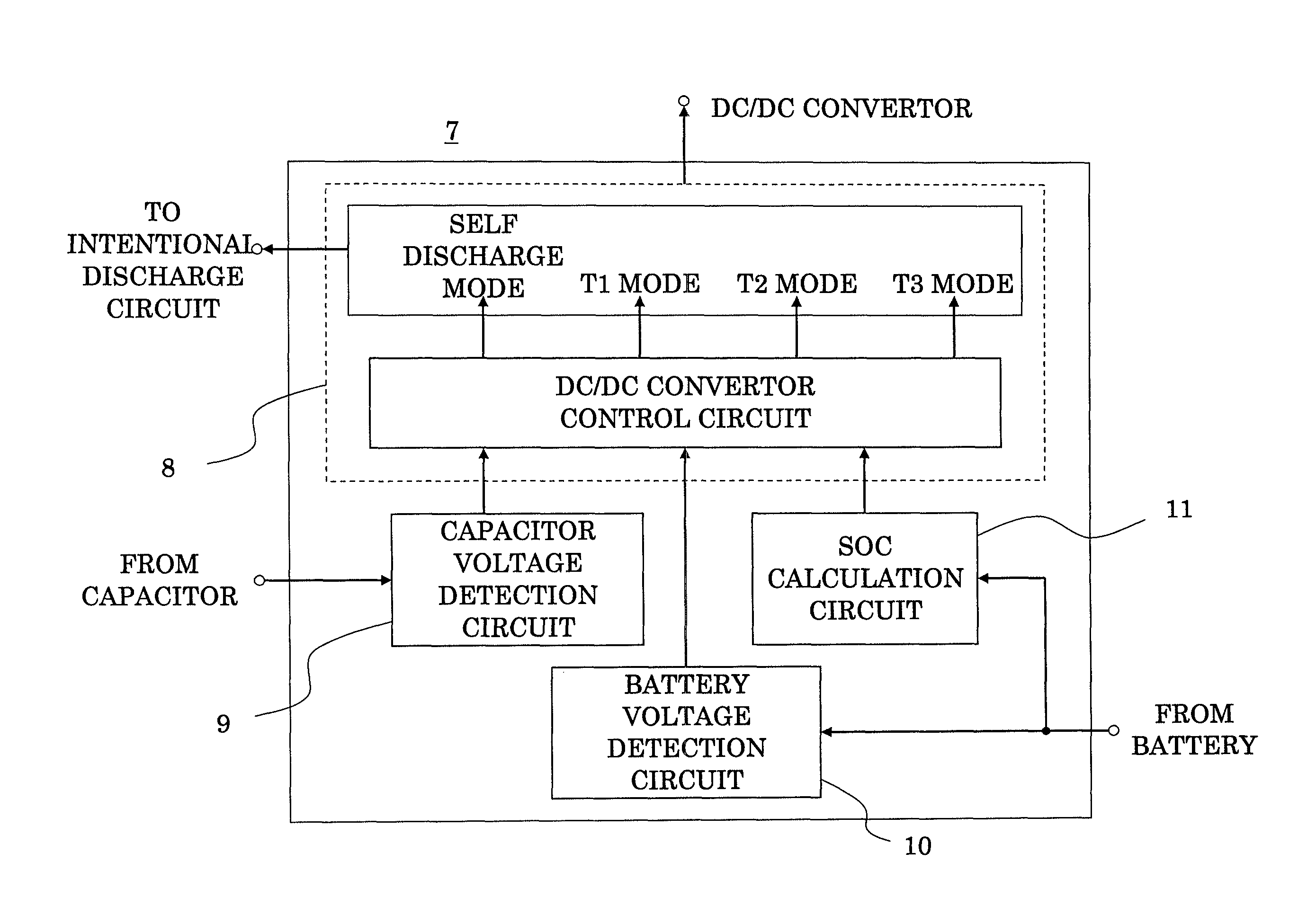
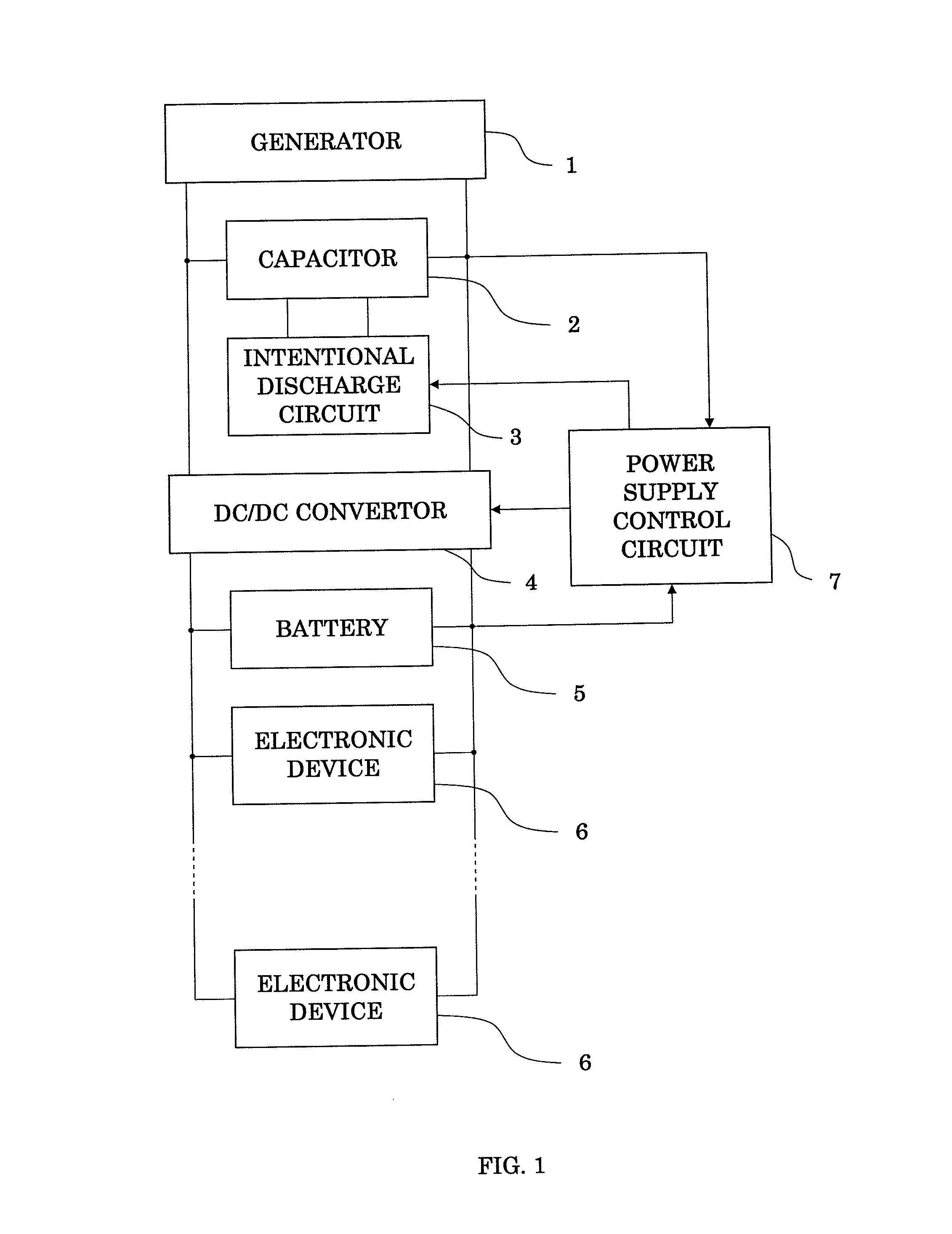
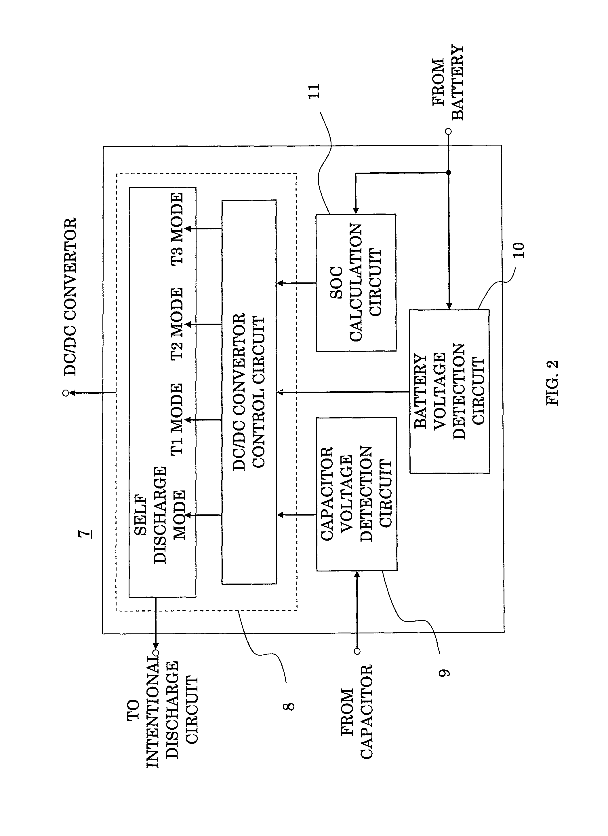
[0021]FIG. 1 is a block diagram illustrating an entire arrangement of the power supply device for vehicle, and FIG. 2 is a block diagram illustrating an internal arrangement of the power supply control circuit thereof.

[0022]A power supply device for vehicle in FIG. 1 includes: a generator 1; a capacitor 2 connected to both terminals of the generator 1; a forced discharge circuit 3 forcing an electric power having been stored in the capacitor 2 to discharge; a DC / DC convertor 4 connected in parallel with the capacitor 2; a battery 5 connected in parallel with the DC / DC convertor 4; a load 6 formed of various electronic devices connected to the battery 5; and a power supply control circuit 7 acting to monitor the voltage of the capacitor 2 and the battery 5 and to control the operation of the DC / DC convertor 4 and the forced disc...

embodiment 2

[0037]In the foregoing first embodiment, the predetermined period after the vehicle engine has been stopped is assumed to be T1; whereas by monitoring whether or not the voltage of the capacitor 2 is varied, that is, whether or not the charge operation or discharge operation of the capacitor 2 is conducted at the power supply control circuit 7, a state of no charge-discharge operation can be determined to be the stop of operation. By letting a predetermined period after the above-mentioned determination T1, the vehicle engine needs not to be externally stopped, that is, the OFF signal of the ignition switch of the vehicle needs not to be inputted, thus enabling to reduce the number of external input terminals of the power supply control circuit 7.

embodiment 3

[0038]Furthermore, in this third embodiment, by the provision of a temperature sensor, temperature rise of a cooling water of the vehicle is determined to be the operation start of the engine, and the drop of water temperature to a predetermined temperature is determined to be the lapse of a predetermined time period from the operation stop of the engine. In the first and second embodiments, a microcomputer forms the power supply control circuit 7 illustrated in FIG. 2 and the time lapse is counted using this microcomputer; whereas in this third embodiment, the time lapse is not counted using a microcomputer, but it is set such that the time point at which a water temperature drops to a predetermined temperature is regarded as when a predetermined time period has passed from the stop of operation, and the discharge to a battery is conducted. Accordingly, the function of monitoring the charge or discharge time period of the capacitor 2 can be simplified, thus enabling to obtain a mor...


PUM


Abstract

The invention has an object of providing a power supply device for vehicle of high efficiency while keeping longer service life of a capacitor. By supplying an electric power of a capacitor to various electronic devices for a first predetermined time period after a vehicle engine has been stopped and discharging an electric power of the capacitor to a battery for a second predetermined time period after the first predetermined time period has ended, the voltage of the capacitor is reduced. By forcing the electric power of the capacitor to discharge at a forced discharge circuit until the voltage of the capacitor is substantially equal to a predetermined voltage after the second predetermined time period has ended, the time period during which the capacitor is held at a high voltage is made shorter. Longer service life of the capacitor and higher efficiency of the power supply device can be achieved.

Description

BACKGROUND OF THE INVENTION[0001]1. Field of the Invention[0002]The present invention relates to a power supply device for vehicle and, more particularly, to a power supply device for vehicle using a capacitor in combination.[0003]2. Description of the Prior Art[0004]It is a recent trend that, to be friendly to environments or to improve fuel efficiency, automobiles having an idling-stop function to stop the operation of engine on the occasion of making a stop or an electric power steering for reducing an engine load are commercially available. Further, a hybrid system for positively assisting engine drive is assumed to come into wide use in the future. Furthermore, as to the braking of vehicles, e.g., a regenerative brake system to recover an electric energy from a braking energy is practically utilized.[0005]As described above, although an electric power that automobiles require tends to increase from now on, a problem exits in that a secondary battery cannot sufficiently be charg...

Claims


Application Information

Patent Timeline
Patent Type & Authority Patents(United States)
IPC IPC(8): B60L11/00B60L11/12B60L50/15
CPCB60L11/005B60L11/126B60L2240/445Y02T10/6217Y02T10/7005Y02T10/7022Y02T10/7077B60L50/40B60L50/62Y02T10/62Y02T10/70Y02T10/7072
Inventor SONE, MITSUOKIHARA, NOBUHIROUEMURA, FUMITO
Owner MITSUBISHI ELECTRIC CORP
Why Eureka
Try Eureka