Light irradiation type heat treatment apparatus
a heat treatment apparatus and light irradiation technology, applied in electrical appliances, ohmic-resistance heating devices, ohmic-resistance heating, etc., can solve the problems of insufficient variation in temperature distribution, and high degree of convex so as to improve the in-plane uniformity of illuminance distribution
- Summary
- Abstract
- Description
- Claims
- Application Information
AI Technical Summary
Benefits of technology
Problems solved by technology
Method used
Image
Examples
first preferred embodiment
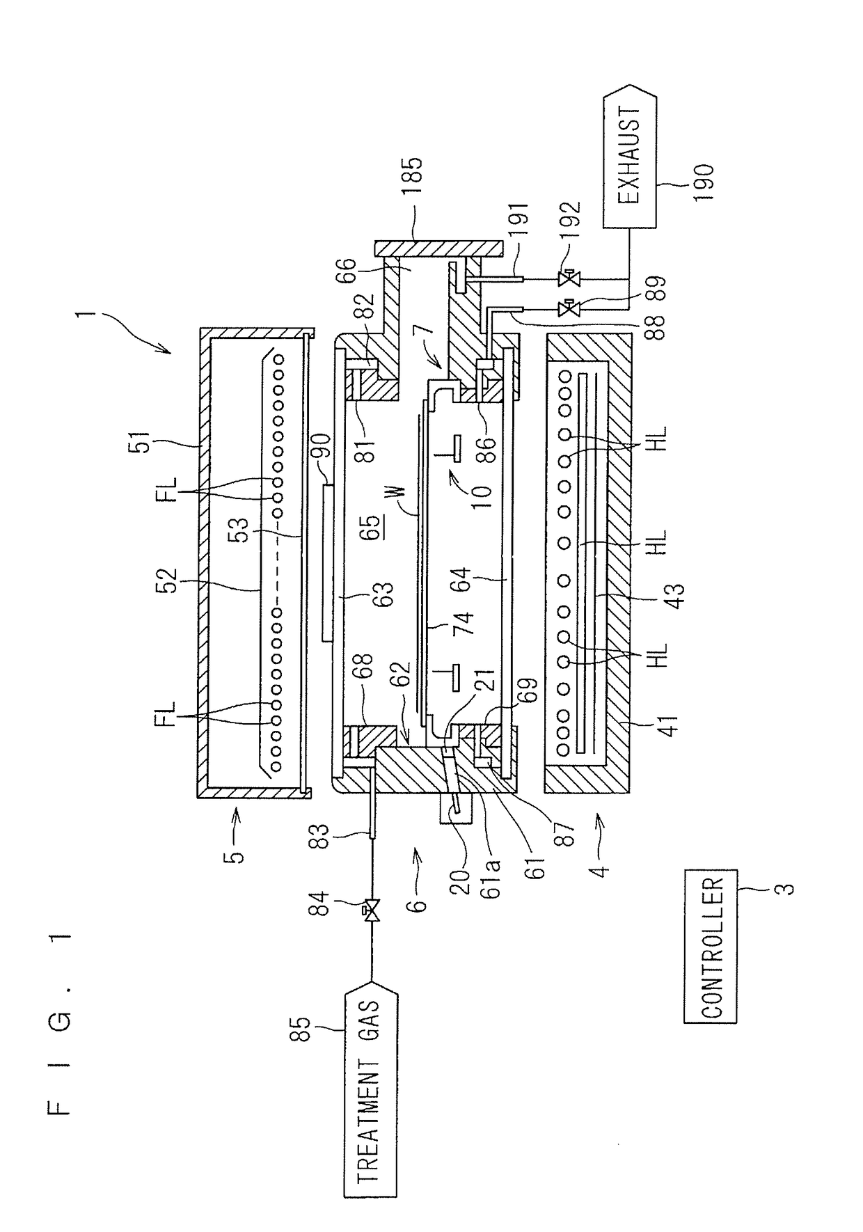
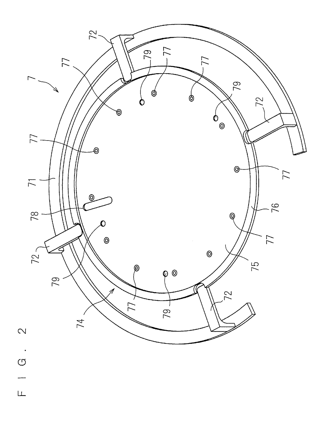
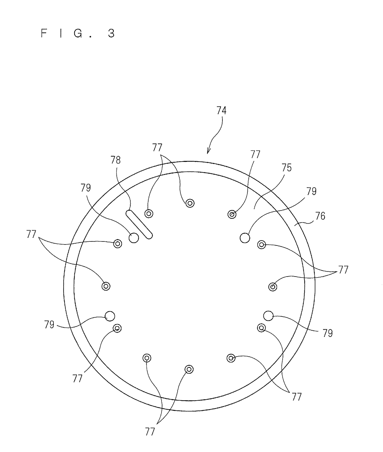
[0043]FIG. 1 is a longitudinal sectional view showing a configuration of a heat treatment apparatus 1 according to the present invention. The heat treatment apparatus 1 of FIG. 1 is a flash lamp annealer for irradiating a disk-shaped semiconductor wafer W serving as a substrate with flashes of light to heat the semiconductor wafer W. The size of the semiconductor wafer W to be treated is not particularly limited. For example, the semiconductor wafer W to be treated has a diameter of 300 mm and 450 mm (in the present preferred embodiment, 300 mm). The semiconductor wafer W prior to the transport into the heat treatment apparatus 1 is implanted with impurities. The heat treatment apparatus 1 performs a heating treatment on the semiconductor wafer W to thereby activate the impurities implanted in the semiconductor wafer W. It should be noted that the dimensions of components and the number of components are shown in exaggeration or in simplified form, as appropriate, in FIG. 1 and the ...
second preferred embodiment
[0097]Next, a second preferred embodiment according to the present invention will be described. The heat treatment apparatus 1 according to the second preferred embodiment is generally similar in overall configuration to that according to the first preferred embodiment. A procedure for the treatment of a semiconductor wafer W in the heat treatment apparatus 1 according to the second preferred embodiment is also similar to that according to the first preferred embodiment. The second preferred embodiment differs from the first preferred embodiment in the form of the light diffusion plate.
[0098]FIG. 12 and FIG. 13 are each a perspective view showing the entire external appearance of a light diffusion plate according to the second preferred embodiment of the present invention. A light diffusion plate 280 shown in FIG. 12 includes a disk-shaped quartz plate having an upper surface provided with a plurality of grooves 281 each having an inclined surface 282. The grooves 281 are formed lin...
third preferred embodiment
[0103]Next, a third preferred embodiment according to the present invention will be described. The heat treatment apparatus 1 according to the third preferred embodiment is generally similar in overall configuration to that according to the first preferred embodiment. A procedure for the treatment of a semiconductor wafer W in the heat treatment apparatus 1 according to the third preferred embodiment is also similar to that according to the first preferred embodiment. The third preferred embodiment differs from the first preferred embodiment in the form of the light diffusion plate.
[0104]FIG. 14 is a perspective view showing the entire external appearance of a light diffusion plate 390 according to the third preferred embodiment of the present invention. The light diffusion plate 390 according to the third preferred embodiment includes a disk-shaped quartz plate having an upper surface provided with a plurality of grooves 391 each having an inclined surface. The disk-shaped light di...
PUM
 Abstract
Description
Claims
Application Information
 - R&D
- Intellectual Property
- Life Sciences
- Materials
- Tech Scout
- Unparalleled Data Quality
- Higher Quality Content
- 60% Fewer Hallucinations
Browse by: Latest US Patents, China's latest patents, Technical Efficacy Thesaurus, Application Domain, Technology Topic, Popular Technical Reports.
© 2025 PatSnap. All rights reserved.Legal|Privacy policy|Modern Slavery Act Transparency Statement|Sitemap|About US| Contact US: help@patsnap.com


