Method for designing LED plane light source structure

A design method and technology of plane light source, applied in the direction of plane light source, light source, electric light source, etc.

Inactive Publication Date: 2009-10-21
董学文
View PDF0 Cites 7 Cited by
  • Summary
  • Abstract
  • Description
  • Claims
  • Application Information

AI Technical Summary

Problems solved by technology

[0004] The problem solved by the present invention is to provide a design method for the structure of the LED planar light source, which can effectively improve the utilization rate of the light source and the uniformity of the brightness of the light source.

Method used


Image

  • Method for designing LED plane light source structure
  • Method for designing LED plane light source structure
  • Method for designing LED plane light source structure

Examples


Embodiment 1

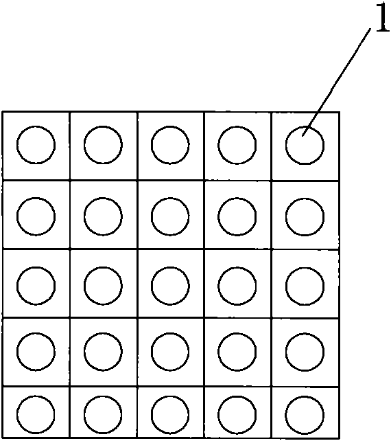
[0026] A method for designing a LED planar light source structure, the specific steps are as follows:

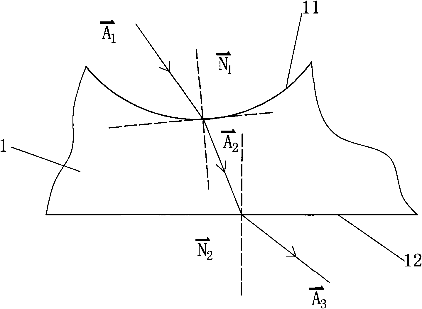
[0027] Such as figure 1 As shown, according to the law of conservation of energy and the law of conservation of luminous flux, the relationship equation between the energy distribution of the light source and the energy distribution of the target illuminated surface is established. The light source uses a Lambertian light-emitting diode, namely Where I is the central light intensity, and a ray incident on the free-form surface 11 of the light-transmitting body 1 is a vector After being refracted by the free-form surface 11, the light enters the medium made of optical resin or engineering plastic, at this time the light is a vector The light on the light-emitting surface 12 of the light-transmitting body enters the air layer from the light-emitting surface 12, and now the light is in is the angle of the light rays from the light source, is the angle of light inciden...

Embodiment 2

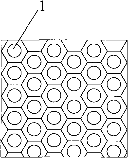
[0041] Such as image 3 The light source design steps and light design steps of the second embodiment shown are the same as those in the first embodiment, except that in the design step of the solid model of the free-form surface of the light-transmitting body, the shape of the solid model of the free-form surface of the light-transmitting body is made into a hexagonal shape. In the design step of the light guide plate, the solid model of the free-form surface of the hexagonal light-transmitting body is combined according to the method of honeycomb staggered arrangement to obtain an integrated light guide plate with dimming ability.

Embodiment 3

[0043] Such as image 3 As shown, the design steps of the light source, the light source and the solid model of the free-form surface of the light-transmitting body in the third embodiment are the same as those in the first embodiment. The solid model is combined according to the method of honeycomb staggered arrangement to obtain an integrated light guide plate with dimming ability.


PUM


Abstract

The invention discloses a method for designing an LED plane light source structure, which comprises the following steps: in step of designing a light source, establishing a relation equation between the energy distribution of the light source and the energy distribution of a target illuminated surface; in step of designing beam, establishing a relation equation between the beam of each angle of the light source and the beam of each point of the illuminated surface; in step of designing entity models of a free curved surface of a transparent body, calculating two relation equations and combining a calculating result with reverse engineering modeling to obtain the entity models of the free curved surface of the transparent body; and in step of designing a light guide plate, combining the entity models of the free curved surface of the transparent body to form the light guide plate with an integrated structure through various arrangement modes. The manufactured LED plane light source structure has high utilization rate of light energy, effectively reduces the effect of dizziness, improves the brightness uniformity of the plane light source and the illumination uniformity of the irradiated target surface and has attractive appearance, practicality and energy conservation.

Description

technical field [0001] The invention relates to a design method of a semiconductor lighting device, in particular to a design method of an LED plane light source. Background technique [0002] With the continuous improvement of LED manufacturing technology, its luminous efficacy continues to rise. Up to now, the luminous efficacy of high-power white LEDs has reached 100lm / w, and the luminous efficacy of stable products is also above 90lm / w. This light effect makes the application of LED more and more widely, including the field of backlight that has been widely used and the field of general lighting that will be widely used in the field of general lighting. [0003] Although the LED light source has a long service life and low energy consumption, but the LED is a point light source, which only emits light into the half space, resulting in two adverse effects: one is that the light emitted by the light source directly shines on the ground and the illuminance distribution is u...

Claims


Application Information

Patent Timeline
Patent Type & Authority Applications(China)
IPC IPC(8): F21S2/00F21V8/00H01L33/00G06F17/50F21Y101/02F21Y105/00F21K9/20F21Y105/16F21Y115/10
Inventor 江程董学文
Owner 董学文
Why Eureka
Try Eureka