LED flat light source structure

A planar light source and curved surface technology, applied in the field of LED planar light source structure, can solve the problems of increased difficulty in optical design, inconspicuous effect, and low light utilization rate of light source, etc., to achieve glare reduction effect, convenient expansion, and high light energy utilization rate Effect

Inactive Publication Date: 2009-10-21
董学文
View PDF0 Cites 7 Cited by
  • Summary
  • Abstract
  • Description
  • Claims
  • Application Information

AI Technical Summary

Problems solved by technology

[0004] At present, LED light sources are used in planar light sources, such as in the field of backlights. In the field of backlights, they can be divided into side-light and direct-light structures according to the distribution of light sources. Increase, the difficulty of optical design of the side-light type also increases, the biggest disadvantage of the side-light type is that the light utilization rate of the light source is very small, only about 50%, and LED is used in the ceiling lamp, which is relatively rare at present, occasionally The products that can be seen are simply adding a frosted glass or a diffuse reflection plate on the surface, but the effect is not very obvious, and it cannot fundamentally solve the problem of uneven brightness distribution

Method used


Image

  • LED flat light source structure
  • LED flat light source structure
  • LED flat light source structure

Examples


Embodiment 1

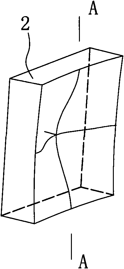
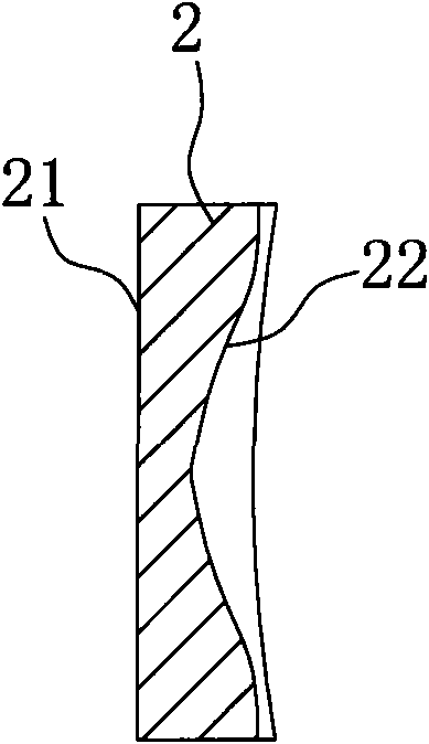
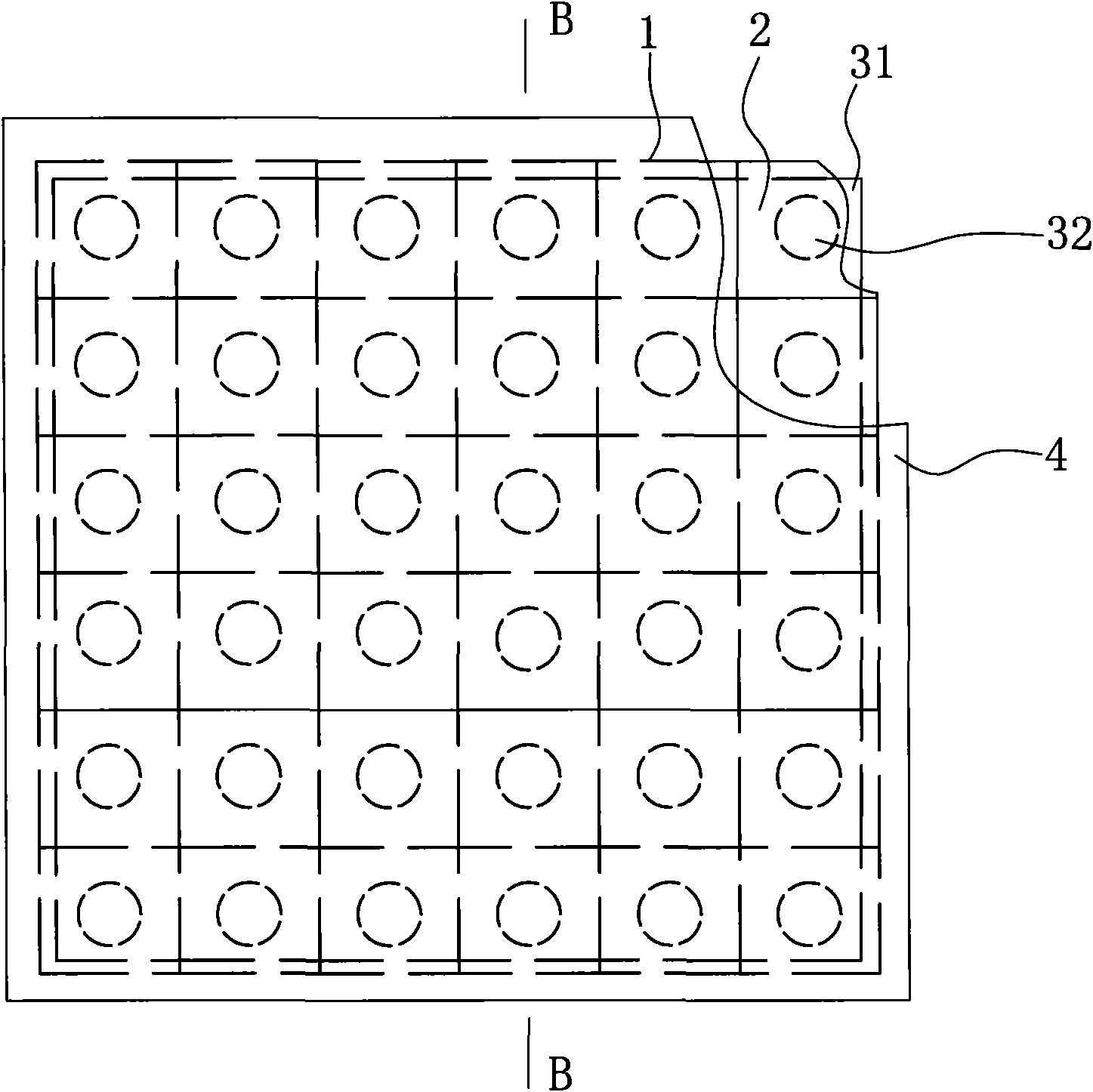
[0025] Such as figure 2 , figure 2 The LED planar light source structure of Embodiment 1 of the present invention shown in (a) includes an aluminum substrate 3, on which several LED light-emitting diodes are installed as illuminants 32, and the front of the several illuminants 32 is provided with a The light guide plate 1 is provided with a diffuse transmission plate 4 in front of the light guide plate 1 to further soften the light, so that the light distribution close to the same illuminance becomes the light distribution close to the same brightness, so as to improve the visual comfort. Such as figure 1 , figure 1 As shown in (a), the light guide plate 1 is composed of several square light guide plate units 2 with free-form surfaces 22 arranged in warp and weft into an integrated structure, which is simple in structure and easy to manufacture. The lower end surface of the light guide plate unit 2 is a light-emitting surface 21, and the other side of the light guide plat...

Embodiment 2

[0027] Such as Figure 4 , Figure 4 (a) shows the LED planar light source structure of Embodiment 2 of the present invention. This structure is roughly the same as Embodiment 1. The difference is that the light guide plate unit 2 of the LED planar light source structure is a regular hexagon, and the light guide plate 1 is made of The regular hexagonal light guide plate units 2 are staggered in a honeycomb form to form an integrated structure, which has a compact structure and a beautiful appearance.

[0028] The above-mentioned two embodiments are only preferred structures of the present invention, and these two structures can achieve better illumination effects. The light source of the LED forms a circular light spot with a radius of 3 meters through the light guide plate unit 2, and because the indoor illuminance needs to take into account the visual Comfortable, the light-emitting surface 21 of the light guide plate unit 2 is frosted, so that the human eye can see that th...


PUM


Abstract

The invention discloses an LED flat light source structure, which comprises an aluminum substrate; the aluminum substrate is adhered with a reflective membrane and is provided with a plurality of luminous bodies; the front of the plurality of the luminous bodies is provided with a light guide plate for diffusing light; the front of the light guide plate is provided with a diffuse transmission plate; and the wall of the light guide plate close to the luminous bodies is provided with freedom surfaces which correspond to the luminous bodies and are used for refracting the light. Illuminators with the two-dimensional and rotationally symmetrical freedom surfaces refract the light so as to increase the radiation area of LED point sources and reduce the glare effect; the LED luminous bodies and the illuminator are arranged one-to-one, so that the flat luminous source structure is changeable according to the actual requirement, is convenient to extend, and can be used in a plurality of occasions.

Description

technical field [0001] The invention relates to the technical field of semiconductor lighting, in particular to an LED planar light source structure. Background technique [0002] After the electric light source has gone through the three stages of incandescent lamp, fluorescent lamp and high-intensity gas discharge lamp, people now generally believe that LED electric light source is the most promising new light source. It has the advantages of high brightness, good directionality, and fast reflection speed. More importantly, LEDs have huge advantages in terms of power consumption and lifespan. With the continuous improvement of LED manufacturing technology, its luminous efficacy continues to rise. Up to now, the luminous efficacy of high-power white LEDs has reached 100lm / w, and the luminous efficacy of stable products is also above 90lm / w. This light effect makes the application of LED more and more widely, including the field of backlight that has been widely used and th...

Claims


Application Information

Patent Timeline
Patent Type & Authority Applications(China)
IPC IPC(8): F21S2/00F21V8/00F21V7/22F21V5/08F21Y101/02F21Y105/00F21K9/20F21Y105/10F21Y115/10
Inventor 江程董学文
Owner 董学文
Why Eureka
Try Eureka