Wireless charging device and charging method thereof

A technology of wireless charging and charging method, which is applied to circuit devices, battery circuit devices, current collectors, etc., can solve the problems of short wireless charging distance, short charging distance, and reduced efficiency, and achieves wide irradiation area, high charging efficiency, and high performance. good effect

Inactive Publication Date: 2017-05-31
HUNAN GOKE MICROELECTRONICS
View PDF4 Cites 7 Cited by
  • Summary
  • Abstract
  • Description
  • Claims
  • Application Information

AI Technical Summary

Problems solved by technology

[0006] The magnetic induction wireless charging device achieves the purpose of wireless energy transmission through the coupling of the electromagnetic field between the coils, but the technology realizes wireless charging at a short distance, and the horizontal movement of the coil will also cause a significant decrease in efficiency, and even charging cannot be realized. The experience is poor; the principle of the magnetic resonance wireless charging device is similar to the magnetic induction method. Although the horizontal displacement has relatively little effect on the efficiency, the charging distance is still relatively short.
That is to say, the use of the wireless charging method of the related technology is greatly affected by the distance, which limits the application of the wireless charging method of the related technology

Method used


Image

  • Wireless charging device and charging method thereof
  • Wireless charging device and charging method thereof
  • Wireless charging device and charging method thereof

Examples


Embodiment Construction

[0031] The present invention will be further described below in conjunction with the accompanying drawings and embodiments.

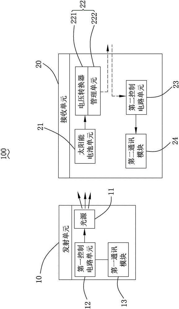
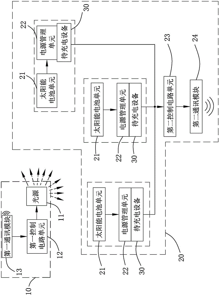
[0032] Please also see Figure 1-2 ,in, figure 1 It is a structural block diagram of the wireless charging device of the present invention; figure 2 It is a schematic diagram of the structure of the wireless charging device of the present invention and the device to be charged when charging. The present invention provides a wireless charging device 100, which includes a transmitting unit 10 for providing light energy and a receiving unit 20 for receiving light energy and converting it into electrical energy for output. The transmitting unit 10 and the receiving unit 20 are in a wireless connection relationship.

[0033] The emitting unit 10 includes a light source 11 , a first control circuit unit 12 and a first communication module 13 .

[0034] The light source 11 is used to provide illumination, and in this embodiment, the light source is an LED...


PUM


Abstract

The invention provides a wireless charging device. The wireless charging device comprises a transmitting unit for providing light energy and a receiving unit for receiving the light energy, converting the light energy into electric energy and then outputting the electric energy, wherein the transmitting unit comprises a light source and a first control circuit unit for controlling the light source to switch on or off; the receiving unit comprises a solar battery unit and a power supply management unit; the solar battery unit is used for absorbing light rays emitted by the light source and converting the light rays into electric energy; the power supply management unit is electrically connected with the solar battery unit; the power supply management unit comprises a voltage converter and a management unit; the voltage converter is used for receiving the electric energy generated by the solar battery unit and converting the electric energy into rated voltage to output; and the management unit is used for charging to-be-charged equipment by the output rated voltage. The invention also provides a charging method of the wireless charging device. Compared with the prior art, the wireless charging device and the charging method thereof have the advantages of long wireless charging distance and good user experience.

Description

[0001] 【Technical field】 [0002] The invention relates to a charging device, in particular to a wireless charging device and a charging method thereof. [0003] 【Background technique】 [0004] With the development of modern technology, more and more electronic devices are used in family life, and the electronic devices all need electric energy to maintain their normal work. In order to meet people's needs, charging equipment continues to innovate, and wireless charging slowly begins to occupy a place in the traditional wired charging. [0005] The related art wireless charging method includes a magnetic induction method wireless charging device and a magnetic resonance method wireless charging device. [0006] The magnetic induction wireless charging device achieves the purpose of wireless energy transmission through the coupling of the electromagnetic field between the coils, but the technology realizes wireless charging at a short distance, and the horizontal movement of th...

Claims


Application Information

Patent Timeline
Patent Type & Authority Applications(China)
IPC IPC(8): H02J50/30H02J7/00
CPCH02J7/025
Inventor 李天望姜黎万鹏刘鸣凯袁涛
Owner HUNAN GOKE MICROELECTRONICS
Why Eureka
Try Eureka